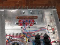
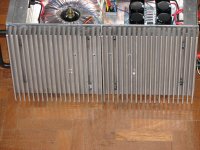
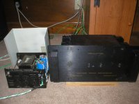
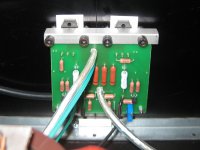
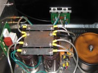
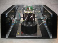
More details 🙂
......
why you choose to use styrofoam between your mosfets and heatsink ?

> why you choose to use styrofoam between your mosfets and heatsink ?
For once, I like your sense of humour.
Quite british, this one.
😉
Patrick
For once, I like your sense of humour.
Quite british, this one.
😉
Patrick
I need that type of heat sinks. Where did you get them? That cabinet its looking really good.
I know, that you want to get the typ of heatsinks from vitalica.
But I will try to help you.
Maybe I use the same heatsinks you have seen in #389, but not so high.
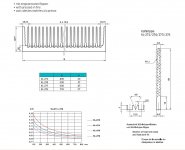
My heatsinks are from seifert electronic >> KL-274
500 x 200 x 84mm 0,1K/W
Seifert-Electronic - Produkte
See my screenshot of the datasheet
You also get similar products from fischer electronic
See PDF Attachment
Sorry that I have only the german data.
Attachments
Last edited:
why you choose to use styrofoam between your mosfets and heatsink ?

Your heatsinks get not so hot!!😀😀😀
I have really much fun here.
Salomon,
Firstly very kind of you to put up the link to Seifert. I have used them for years, and am a satisfied customer.
However, I wish to point out that the optimal height for these sinks are not necessarily 200mm. These welded fin heatsinks (whether from Seifert or Fischer) has a 12.5mm fin pitch (as opposed to many extruded sinks with 10mm pitch). The increased pitch reduced air flow resistance between fins substantially (by almost a factor of 2). Hence there is still substantial performance gain going from 200mm to e.g. 400mm. One can see that from the graph you attached in post #424. Whether it is necessary or not depends on how much heat you want to dissipate or how low a temperature you want on the sinks. Of course they cost more with a 400mm height.
Patrick
Hi all
Not a real finished amp BUT it's working !
Thanks to all especially to Mr Nelson PASS, BrianGT and to all the other folks who gave me a helping hand 😉
http://www.diyaudio.com/forums/pass-labs/52188-new-aleph-mini-pcb-gb-139.html#post2372520
Not a real finished amp BUT it's working !
Thanks to all especially to Mr Nelson PASS, BrianGT and to all the other folks who gave me a helping hand 😉
http://www.diyaudio.com/forums/pass-labs/52188-new-aleph-mini-pcb-gb-139.html#post2372520
My F5 clone effort
Hi,
After more than 6 months, I have managed to bring the F5 clone project to a closure. Very satisfied with the outcome in terms of sound quality and experience.
Totally new level of sonic experience listening to this amp through my FE206E back loaded horn fullrangers. Though I am getting used to signature F5 clarity in the middle and upper frequencies and slightly weaker bass.
The entire design is fully to the spec and no mods. Set up was a breeze. Heatsinks are extra large (two of them coupled by a copper flat for each side). After 2.5 hours the amp gets moderately warm and I can touch the heatsink for a long time without burning myself.
Thanks to Mr. Pass for this great design and all the experts on this forum, whose posts have helped me immensely in executing this well.
Cheers.
Attachments
F5 clone
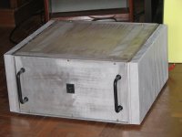
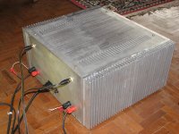
I reused a Sumo Andromeda case for my F5. I use a 1/4" 4" x 8" block of
copper as a heat spreader on the heatsinks and used high preformance
insulators. I used the case from a bad power stablizier for my external
power supply. The external power supply has a pair of 40,000uf caps then
in the amp case I use a pair of 15,000uf caps for each chanel decoupled
from the external power supply with .1ohm resistors. Thanks Nelson for
letting us have this fine design!
Attachments
RE: My F5 clone effort
Hi Anil,
great work, I bought the F5 PCBs long time back but never had chance to finish it. Given the parts and resources availability in India, your build is great. Just one comment, tidy up the internal wiring, route the wires along the edges it looks even greater then. Have fun.
Thanks,
Routhun
Hi Anil,
great work, I bought the F5 PCBs long time back but never had chance to finish it. Given the parts and resources availability in India, your build is great. Just one comment, tidy up the internal wiring, route the wires along the edges it looks even greater then. Have fun.
Thanks,
Routhun
Show us the porn, we all want to see that copperI reused a Sumo Andromeda case for my F5. I use a 1/4" 4" x 8" block of
copper as a heat spreader on the heatsinks and used high preformance
insulators. I used the case from a bad power stablizier for my external
power supply. The external power supply has a pair of 40,000uf caps then
in the amp case I use a pair of 15,000uf caps for each chanel decoupled
from the external power supply with .1ohm resistors. Thanks Nelson for
letting us have this fine design!

Hi Anil,
great work, I bought the F5 PCBs long time back but never had chance to finish it. Given the parts and resources availability in India, your build is great. Just one comment, tidy up the internal wiring, route the wires along the edges it looks even greater then. Have fun.
Thanks,
Routhun
Thanks. I agree, I need to tidy up the wiring. Now that the amp has stabilized, I will use some cable ties.
Cheers.
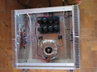
Under the capacitors you find the two 600VA transformers.
You can see it on the picture.
The complete weight is 51,4 kg
The torobars are cooled because the high current (7A).
They are thermally coupled with the U-shaped Heatsink. You see it grey between coils and the Heatsink.
The black heatsinks over the coils are for the softrecovery rectifiers. They need good cooling.
What an amazing build! I was just looking for inspriration how to build my ExtremA amp and Salomon's pass amp seems to be a benchmark.
Too bad the website of Salomon is down? Is it coming online again with some additional pictures how you build the amp?
Scanspeakman
If you're contemplating Torobars for the PS of the ExtremeA, read William's WuffWaff thread on his Aleph-X power supply.
(provided you haven't already)
(provided you haven't already)
- Home
- Amplifiers
- Pass Labs
- Pictures of your diy Pass amplifier

