
Sad story. The amplifiers have been in storage and now both seems to go into DC protection mode. Turning off after a few seconds. I seem to recall one had such a problem, and the theory was a bad JFET. Seems I have got myself some labour. But I have borrowed temperature probes. That is a start. More later……and temperature inside is?
I presume you have top covers
if not, just ignore me
Attachments
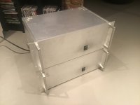

If it’s not isolated from the chassis, it also creates a ‘short turn’ of the trafo’s and thats not a good thing.
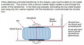
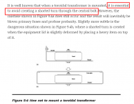
These guys are right. That big metal bar is a bad idea. I would remove it immediately. Mount the toroids with the hardware that they give you when you buy one (bolt, top plate, flat washer, split washer, and nut). Then find some other way to mount that wiring distribution block.
@Giovanni1968
Maybe my eyes are deceiving me, but I do not see anything connected to the center pin on your IEC. Can you show a closer pic?
Best,
Anand.
as Kasey would say - builder's ambition obviously outweighed its talent
small washers on mosfets
no safety GND
shorted Donuts
bunch of unnecessary additional contacts
fancy parts are good, but only if basic things are done correct
small washers on mosfets
no safety GND
shorted Donuts
bunch of unnecessary additional contacts
fancy parts are good, but only if basic things are done correct
And umm….are those F4 boards mounted solely off the terminals of the MOSFETS? What happened to the standoffs? I can see them being optional if the board had output devices on both sides (i.e. Stasis output boards) but when it’s only on one side, I would recommend mounting the standoffs to avoid excessive tension on the MOSFET leads.
Best,
Anand.
Best,
Anand.
I don't see a reason for standoffs on the MOSFET side of the board but a couple on the other side in the corners would be a good idea.
It looks like if Giovanni sorts out these fairly easy-to-resolve details, he should have a very nice amplifier 🙂
It looks like if Giovanni sorts out these fairly easy-to-resolve details, he should have a very nice amplifier 🙂
I don't want to take merit of the build, it was a tech to do it for me but then another one, locally, had to fix some issues with the rectifiers cooling and the soft start.
Now, with the help of the community, I am taking measures to check the voltages across the mosfets to try and find out if the amp is correctly biased as it seems it can't really sound as it should, hopefully I can get down to at least find out if there is something to dial or if the 25W just can't make it with my speakers.
Grazie @ghitus questa è la prima volta che metto le mani in un oggetto del genere se non altro almeno per fare delle misure e spero anche per regolare il bias

- Home
- Amplifiers
- Pass Labs
- Pictures of your diy Pass amplifier