This is posted in the MX2 thread, but belongs here:
Retro: I even use the middle switch to turn on and lite the glass too/
Retro: I even use the middle switch to turn on and lite the glass too/
Attachments

Last edited:
This is posted in the MX2 thread, but belongs here:
Retro: I even use the middle switch to turn on and lite the glass too/
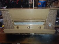
Super cool. Not a Pass amp but your build reminds me of my 1956 console.
This is posted in the MX2 thread, but belongs here:
Retro: I even use the middle switch to turn on and lite the glass too/
Nice, I like it. What amp is that?
that's one thing I'm always asking about
though, this time I ignored that , asking for more porn and counting that heatsinks are more than capable for measly ACA
Choky,
You are surrounded by amplifier porn. No, I should say you ARE amplifier porn 😀

Nice, I like it. What amp is that?
It's an MX2 with the unobtainable parts and all. 😀
It is a Pass amp too, it's the copy of the M2.
Last edited:
Aleph 5
Hello everybody. During quarantine, I started building the aleph 5 amplifier, and of course I started with a case for it. I will change the bolts 🙂, I put these temporarily. And I made of aluminum, legs for him. Sorry for my English.


Hello everybody. During quarantine, I started building the aleph 5 amplifier, and of course I started with a case for it. I will change the bolts 🙂, I put these temporarily. And I made of aluminum, legs for him. Sorry for my English.
Aleph 5
😀 thanks...
the manufacturing process of this amplifier, I will upload here. thanks
@daddysweet - that is beautiful!!! Congratulations. 😀
😀 thanks...
the manufacturing process of this amplifier, I will upload here. thanks
Aleph 5
I looked at this amplifier, and it seemed to me that it looks a little boring. I thought and decided to add the inscription: "ALEPH 5"

I looked at this amplifier, and it seemed to me that it looks a little boring. I thought and decided to add the inscription: "ALEPH 5"
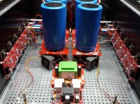
4 chanel Ba3 & balanced Ba3 & bridged Ba3
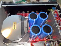
my first whack at an amplifier build ready to drive a my stereo 2 way speakers in class A
can be : balanced ba3 stereo or 4 channel single ended aking for the incoming crossover.
it has packed a lot of goodies like dual thermometer indicating the temperature on the radiators, over temperature protection , dc protection that curently trips 🙂 dince i have -10mV at start that slowly goes to 0 when 55 degrees reached ... the yellow indicator on sides and all pannels are spaced to handle dissipating gracefully the 300w it adsorbs from mains.
Attachments

OK, now that's just cool! 
Do you mind sharing the source for your "safety" boards? Is the DC protection, temp monitoring / temp protection, and soft start all in one assembly?
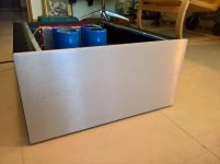
BTW - LOVE the tangle of wires reflected in that gorgeous Toroidy case.
Do you mind sharing the source for your "safety" boards? Is the DC protection, temp monitoring / temp protection, and soft start all in one assembly?
BTW - LOVE the tangle of wires reflected in that gorgeous Toroidy case.
to escucalin
That is a very good build! Looks really cleaned up.
Enjoy your amp!
I also have built 2 versions of the BA-3. Great amp! I call it the 'bass machine' 😀
It also sounds great in the other octaves...
Greets
Dirk
That is a very good build! Looks really cleaned up.
Enjoy your amp!
I also have built 2 versions of the BA-3. Great amp! I call it the 'bass machine' 😀
It also sounds great in the other octaves...
Greets
Dirk
OK, now that's just cool!
Do you mind sharing the source for your "safety" boards? Is the DC protection, temp monitoring / temp protection, and soft start all in one assembly?
BTW - LOVE the tangle of wires reflected in that gorgeous Toroidy case.
ofcourse i do not mind sharing :
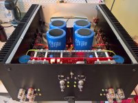
- the DC protection is the speaker protection from the diy audio store and is integrated partially on the shielded back board (the actual relays are just on the back of the speaker posts... a mistage i've made not integrating the posts and relays in their own boards....).
there i've crammed 4 ba3 front ends with positive and negative stabilizers (Salas's shunt) and with the input selector under that horrible shield ... the only one of steel i've got until the custom order comes along.
i've integrated the schematic from the speaker protection and sent only the relay signals on the ribbon around the back and in all the case for lights along with temperature sensing for the thermometers.
The temperature protection is a soft start modified and with big 20 or 40 ohm NTC's i've got from ebay after calculating it takes double for me to build one. The soft start has also temperature protection capability and it makes gentle on the transformer limiting the inrush of the 3mF CLC as calculated with a nice program that draws the loading curve for your specific power supply and helps adjust the delay time .
As an abandoned path i was ready to use a microcontroler and maybe max6616 to handle cooling temperature lights protections and everything but choose to go the hard , and reliable way since inside no controler is safe... it can run HOT.
I've attached a picture with the underbelly ... the lights supply and the thermal and soft start protection from an early stage of building.
Attachments
i'm plain silly... many mistakes and design flaws ... way to many wires ... first build , and no idea of mine except silly and basic logic involved in managing inputs outputs and internal environment.
looks ugly to me ... because i have funds and experience very very limited but is work based on great design and must be shown!!!
looks ugly to me ... because i have funds and experience very very limited but is work based on great design and must be shown!!!
OK, now that's just cool!
........
BTW - LOVE the tangle of wires reflected in that gorgeous Toroidy case.
@ItsAllInMyHead:
...itsallONhishead !!!

Brilliant first amp!
- Home
- Amplifiers
- Pass Labs
- Pictures of your diy Pass amplifier