i have some questions regarding the 1st order allpass.
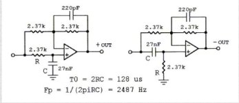
the attached shows the inclusion of 220pF caps.
i have assumed that this is for stability purposes, is that right? and how would you determine its value is sufficient?
if you simulate the two circuits, the 220pF causes a peaking in the HF response for the inverting circuit and rolloff for non-inverting circuit.
Attachments
Nothing more to add to Charlie, but I can say that even placement of a dipole isn't so critical, as long as it's angled to the wall! Ten years ago I was really surprised not being able to locate speakers blindfold, not until very close (less than a foot). Sound of a single speaker or a stereo pair fills the room and still stereo imaging in listening area is very good. How important physical time-alignment is to this I don't know because my speakers have planar mid and tweeter in a plate, aligned with the woofer as well as I can say.
Here a movie clip, recorded with Zoom Q3 . Recordings sadly don't sound like live human perception...
https://drive.google.com/file/d/0Bz...ive_link&resourcekey=0-xudBRXy-1rnBc6X8GIjGMw

Here a movie clip, recorded with Zoom Q3 . Recordings sadly don't sound like live human perception...
https://drive.google.com/file/d/0Bz...ive_link&resourcekey=0-xudBRXy-1rnBc6X8GIjGMw
Last edited:
Yep, those are "angst" capacitors, intended to improve stability. They are IMHO way too large in those circuits, maybe a typo in those diagrams?i have some questions regarding the 1st order allpass.
the attached shows the inclusion of 220pF caps.
i have assumed that this is for stability purposes, is that right? and how would you determine its value is sufficient?
if you simulate the two circuits, the 220pF causes a peaking in the HF response for the inverting circuit and rolloff for non-inverting circuit.
Their purpose is to compensate for the OpAmp's input capacitance and any stray capacitance from the (-)-input to GND and hence should be choosen to have about roughly the same capacitance in order to achieve a stable low "noise gain" of ~2 at RF (1MHz++) frequencies. 22pF...47pF are typical values and a reasonable educated guess.
These circuits are quite low impedance and thus are not very prone to such stability issues to begin with because the resistors dominate the feedback up to very high frequencies before the explicit and hidden capacitances take over.