Not as well. They are 130V. It's amazing how much difference it makes vs 120V bulb since it's really acting as a resistor 🙂
Thanks though!
Thanks though!
Showing a high-end headphone amplifier I designed. I am planning to release this as a DIY project on the forum in the next few months. That will include a full schematic, BOM, gerber files for PCBs, CAD files for a chassis, build instructions, measurements, etc. This is an expensive project, probably the cost of parts is something like $1.5K given it makes heavy use of Lundahl inductors and a high-quality chassis, but the sound is excellent (in my opinion) and it is very easy to build for someone with a little experience. I can build this amplifier from scratch in 6 hours. There will likely be some forthcoming reviews by some dudes on Head-Fi forum, the first one is on a road trip for demoing purposes. The amplifier was recently featured at the ZMF Headphones table at CanJam SoCal, feedback was very positive.
Here is a general schematic.
View attachment 1094992
Input stage is choke loaded parallel-section 6SL7, cathode biased with Jupiter Cosmos bypass caps. Input stage is capacitor-coupled via Jupiter copper foil film caps to a triode-strapped pentode output stage. The output stage is a transformer-coupled cathode follower, biasing is done by the DCR of the OPT primary winding and some added series resistance. There is no bypass capacitance required in the output stage, which results in excellent clarity, staging, airiness, and dynamics. All voltage gain is done by the choke-loaded 6SL7, it swings over 300Vpk-pk. Each output tube has its own heater winding referenced to its cathode to avoid violating Vhk at peak output swing. Potentiometer cannot exceed 25K given the high Cmiller of the parallel 6SL7. The power supply is a split rail CLCRCRC, it is tube rectified, no semiconductors in this build.
Input tube is mandatory 6SL7 pair
Rectifier are 5V / 2A types - 5AR4, 5V4, 5R4, 5Y3 (although care must be taken with 5Y3 not to overspec DC current)
Output tube are various power pentodes - EL34, KT77, KT88, 6550, 6V6, 6L6, EL37, and many more.
Distortion is very low at normal listening volumes, bandwidth is down < 1dB at 20Hz and 20kHz. There is an ELMA output switch to change for high Z (150ohms and up) and low Z (32-150ohms) headphones. Output impedance on the high Z setting with EL34 outputs is ~17ohms. Output Z on the low Z setting with EL34 outputs is ~5ohms. Output power is around 2W into 32ohms on low Z, 2W into 150ohms on high Z. I will post real measurements when the thread is made.
Pictures of the completed amplifier.
View attachment 1095000
View attachment 1094991
View attachment 1095002
The circuit.
View attachment 1094990
Think people will be interested in building my headphone amplifier? We will see!
I would definitely be interested in an EL34 headphone Amp. My wife and I go to Axpona every year and devote a lot of time to auditioning the headphone amps. This year the best HPA we heard was an EL34 one. It might have been totally different than yours, but who knows, worth a try. Of course the company was using Stax phones to demo it, but I brought my Sennheisers with me and still sounded great, not as great as $12,000 Stax but very good. Wish I remembered the maker, it wasn't cheap so I didn't bother to remember who made it.
Did you post the as-built schematic yet in the tubes section?
Not as well. They are 130V. It's amazing how much difference it makes vs 120V bulb since it's really acting as a resistor 🙂
Thanks though!
Yeah they're going to 130v bulbs a lot now because they last longer. I noticed that seemed to start with the bulbs started coming of Mexico a lot.
as long as the incandescent lamp you use can limit current effectively and prevent serious damage to your equipment, then you can use it...
Last edited:
That makes sense for a lamp limiter, this is the load for an SE MOSFET follower amp though.
If you set 25V across the MOSFET:
With 130V, 300W you get ~1.6A
With 120V, 300W you get ~2A - I find this to be the sweet spot but it'll still hit 95°C This is like using a 22R resistor for load. The bulb "only" uses 90W in this case so I'm not worried about them burning out really.
With 120V, 200Wx2 in parallel, you get ~2.2A
And using a 120V 500W (50 hours for photography) you get 2.5A I measured 110°C heatsink with this set up.

Hi everyone,
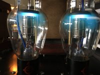
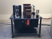
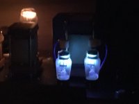
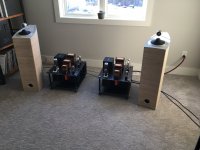
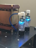
This is my latest creation (Aa driving GM70 monoblocks). Also, I would like to share a new blog that I have created which focuses on my new monoblocks and related topics.
https://ironandglass.squarespace.com/
Hope you enjoy.
Pat
This is my latest creation (Aa driving GM70 monoblocks). Also, I would like to share a new blog that I have created which focuses on my new monoblocks and related topics.
https://ironandglass.squarespace.com/
Hope you enjoy.
Pat
Attachments
-
 final amp43 2.JPG377.8 KB · Views: 321
 -
 final amp83.JPG369.2 KB · Views: 321
 -
 final amp79.JPG186.9 KB · Views: 322
 -
 final amp86.JPG428.3 KB · Views: 497
 -
 final amp80.JPG503.1 KB · Views: 502
 -
 final amp69.JPG360.7 KB · Views: 349
 -
 final amp65.JPG470.8 KB · Views: 473
 -
 final amp66.JPG368.8 KB · Views: 338
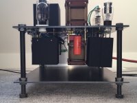
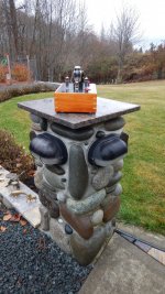
Hey everyone, I just posted another blog entry with photos of my chassis work from 2018. Check it out. Now, these chassis are very subjective. You will either love 'em or hate 'em.
https://ironandglass.squarespace.com/blog/roasted-cauliflower-garlic-dip-t9med-psjc4-mgmks-cnegd
https://ironandglass.squarespace.com/blog/roasted-cauliflower-garlic-dip-t9med-psjc4-mgmks-cnegd
Very creative! I like the use of concrete blocks and iron, looks like the setup would survive a nuclear weapon generated EMP, depending how close it is to the detonation site.Hey everyone, I just posted another blog entry with photos of my chassis work from 2018. Check it out. Now, these chassis are very subjective. You will either love 'em or hate 'em.
https://ironandglass.squarespace.com/blog/roasted-cauliflower-garlic-dip-t9med-psjc4-mgmks-cnegd
A bit too industrial for me but I appreciate being different, doing what is within our means or goals, and finishing a job. It has some elements of green and green woodworking which is damned creative when done in iron. Well done.Hey everyone, I just posted another blog entry with photos of my chassis work from 2018. Check it out. Now, these chassis are very subjective. You will either love 'em or hate 'em.
https://ironandglass.squarespace.com/blog/roasted-cauliflower-garlic-dip-t9med-psjc4-mgmks-cnegd
Dale - I'm glad you noticed the Green and Green overtones. I am a huge fan of their work. If you haven't yet, please make a trip (bucket list) to see one of their homes in Pasadena. Craftsmen like no other.
As in Green Street Pasadena, CA? Or, is it Greene and Greene, architect of the Gamble House?Dale - I'm glad you noticed the Green and Green overtones. I am a huge fan of their work. If you haven't yet, please make a trip (bucket list) to see one of their homes in Pasadena. Craftsmen like no other.
RH Amp
Hello all:
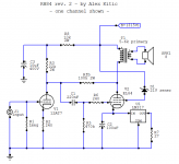
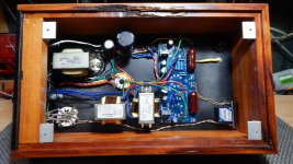
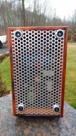
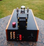
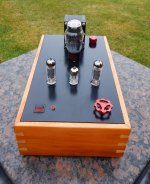
I have completed a build of an Alex Kitic Race Horse amp. I chose to make an RH 6P15P. Which is a derivative of the RH EL84 amp. Below are a few pictures of the completed project. I got a PCB file from a fellow DIYer and am very grateful to him for his kindness and sharing.
I have not completed the testing of it yet, but it sounds very good on the shop speakers. It was an interesting journey and made me think a lot in order to keep it small and sleek. I am quite happy with outcome, my wife likes the presentation and the sound.
I used a 1960's Philco 5U4G rectifier tube. The tube has red label printing on the base so I used that to theme the colour of the controls on the top deck.
There are no visible anchoring screws with the exception of the one "master" screw located on the rear panel which holds the amp chassis to the wood chassis.
I used 1/4 inch (~6mm) Aluminium plate for the amp chassis build and had a good friend weld the top plate to the rear panel. The amp was completed "dry" built to get all items located where I wanted them. All anchor screws are set back by 1/16th inch (~2mm) from the top plate and filled with epoxy resin to give a very clean look. To do this I drilled, taped and cleaned the holes. Then installed 4mm stainless steel screws in the holes, which left about 1/16th inch of space, then filled from the top the remaining space. Sanded the plate to 320 grit, etch primed and painted with satin black. Then left it alone for week to dry, and most importantly, harden.
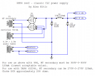
After some fussy attempts at trying to salvage an older transformer I ended up getting a Hammond 270ex for the power supply. B+ is 305vdc.
The output transformers were salvaged from an EL84 amp I pick-up while in China a number of years ago. They have an UL tap that was not used for this amp. I put a 100v Zener diode in to lower the screen voltage for the 6P15P. Input is controled by a 100K ALPS pot.
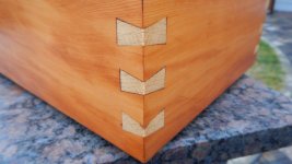
The wood chassis is made from Pacific Yew with Gary Oak bow ties for accent. The bottom panel is 1/8 inch holey aluminium.
The schematic is RH82 v2.
There you go
Enjoy
Hello all:
I have completed a build of an Alex Kitic Race Horse amp. I chose to make an RH 6P15P. Which is a derivative of the RH EL84 amp. Below are a few pictures of the completed project. I got a PCB file from a fellow DIYer and am very grateful to him for his kindness and sharing.
I have not completed the testing of it yet, but it sounds very good on the shop speakers. It was an interesting journey and made me think a lot in order to keep it small and sleek. I am quite happy with outcome, my wife likes the presentation and the sound.
I used a 1960's Philco 5U4G rectifier tube. The tube has red label printing on the base so I used that to theme the colour of the controls on the top deck.
There are no visible anchoring screws with the exception of the one "master" screw located on the rear panel which holds the amp chassis to the wood chassis.
I used 1/4 inch (~6mm) Aluminium plate for the amp chassis build and had a good friend weld the top plate to the rear panel. The amp was completed "dry" built to get all items located where I wanted them. All anchor screws are set back by 1/16th inch (~2mm) from the top plate and filled with epoxy resin to give a very clean look. To do this I drilled, taped and cleaned the holes. Then installed 4mm stainless steel screws in the holes, which left about 1/16th inch of space, then filled from the top the remaining space. Sanded the plate to 320 grit, etch primed and painted with satin black. Then left it alone for week to dry, and most importantly, harden.
After some fussy attempts at trying to salvage an older transformer I ended up getting a Hammond 270ex for the power supply. B+ is 305vdc.
The output transformers were salvaged from an EL84 amp I pick-up while in China a number of years ago. They have an UL tap that was not used for this amp. I put a 100v Zener diode in to lower the screen voltage for the 6P15P. Input is controled by a 100K ALPS pot.
The wood chassis is made from Pacific Yew with Gary Oak bow ties for accent. The bottom panel is 1/8 inch holey aluminium.
The schematic is RH82 v2.
There you go
Enjoy
Attachments

I mean it's dusty AF because I'm lazy and live in a dusty area (condo construction) but it's nice to hear how great these "prototype" amps sound.
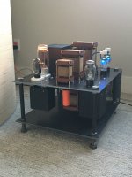
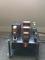
Now I have circuit boards but this (pair) is the last existing point to point tube amp(s) I still have.
572VA PT, 3300uF soup can cap, Mono 113W* RMS sine wave @ 30Hz triode power using PPP 6P45S measured using 6R resistive loading. OPT made from 2x 250VA VPT18-13800 interleaved
Heaters and B+ for front end provided by linear 11.7V instead of my usual SMPS designs.
These were the only amps I made where I used heater cord for the top cap connections.'
The power comsumption is almost 300W for it to sit there, but at least I didn't need to buy a heatsink LMAO
Last edited:
I could see the smile on his face when he described it on the phone. He's modest but some things you just can't hide.How does it sound Scott?
Hey, I like those bad boys! Found pair of 6KG6's that are on my bucket list to do something with-I mean it's dusty AF because I'm lazy and live in a dusty area (condo construction) but it's nice to hear how great these "prototype" amps sound.
Now I have circuit boards but this (pair) is the last existing point to point tube amp(s) I still have.
572VA PT, 3300uF soup can cap, Mono 113W* RMS sine wave @ 30Hz triode power using PPP 6P45S measured using 6R resistive loading. OPT made from 2x 250VA VPT18-13800 interleaved
Heaters and B+ for front end provided by linear 11.7V instead of my usual SMPS designs.
These were the only amps I made where I used heater cord for the top cap connections.'
The power comsumption is almost 300W for it to sit there, but at least I didn't need to buy a heatsink LMAO
View attachment 1113480
So you like the way they sound.. eh? 100+ watts? Then could that particulate matter showing have come from your ceiling... not the construction zone??
Inquiring minds want to know ;<)
Jim
Even more dusty is the "Stupendous" 6P1P amp that amazes me because it can make over 90DB of sound in class A using cheap tubes and parts - and it sounds good 🙂
More info for those who care...
Spacing between speakers ~7 feet and ears 7 feet. Roughly a triangle.. Maybe it could be louder but I didn't try for the limit of clipping.


More info for those who care...
Spacing between speakers ~7 feet and ears 7 feet. Roughly a triangle.. Maybe it could be louder but I didn't try for the limit of clipping.
- Home
- Amplifiers
- Tubes / Valves
- Photo Gallery