
Not my first build but my first post here in the forum. Just a "quick'n dirty" interim solution for volume and loudness control (bass boost only), with least effort as possible. As a preparation for my next project. Loudness circuit borrowed from here
BR Sven
BR Sven
Attachments


It IS a very nice job with (as far as I can correctly interpret those pictures) quality components.
For me, high end means also very good measuring characteristics of the design. And these did not accompany the pictures.
But I am feeling a bit unpleasant with the content Ian's first response. Was that really necessary?
Here are some basic measurements of the headphone amp from a few posts back. All are from the right channel using GZ34, 6SU7GTY, and EL34 into 32ohm and 300ohm dummy loads using low and high Z output settings respectively. Using Jan Didden's Autoranger paired with a MOTU M4 interface.
1mW into 32ohm

1W into 32ohm

1mW into 300ohm

500mW into 300ohm

Frequency response 1mW into 32ohm

Frequency response 1mW into 300ohm

Those are really very good specifications! Of course 1W into 32 or 300 Ohms is not practical (it will blow your ear drums out of your
head) it shows the very good quality of your design.
But that is my humble opinion of course.
Thanks! Yes of course, I just wanted to illustrate the distortion is quite low even at higher power outputs. In terms of the frequency response, it is down about 0.8dB at 20Hz and 20kHz. Output impedance on low Z is 5ohms, on high Z 17 ohms.
I'll have to redo these measurements at some point, just a quick and dirty set here, the harmonics at 8kHz and 16kHz appear to be artifacts since they are present on loopback without the amplifier in the path, I suspect something is up with my ADC. Noise floor is higher than expected too. Anyway, I'll leave it there for now and post finalized measurements down the road.
That I do not understand. If I look at the 1mW into 300 Ohm spectrum then I see a noise floor which is -80 dB lower than the first harmonic.I'll have to redo these measurements at some point, just a quick and dirty set here, the harmonics at 8kHz and 16kHz appear to be artifacts since they are present on loopback without the amplifier in the path, I suspect something is up with my ADC. Noise floor is higher than expected too. Anyway, I'll leave it there for now and post finalized measurements down the road.
So, what is the problem?
That I do not understand. If I look at the 1mW into 300 Ohm spectrum then I see a noise floor which is -80 dB lower than the first harmonic.
So, what is the problem?
It isn't a problem, I just don't think the measurement is accurate. The noise floor is essentially identical on loopback of my interface with and without the amplifier in the path, it should be significantly lower with the amplifier removed based on previous loopback measurements, so it appears the interface is making a significant contribution when it shouldn't.
Ah, I understand. But that is something which I cannot interpret because I do not have access to your set-up 🙂It isn't a problem, I just don't think the measurement is accurate. The noise floor is essentially identical on loopback of my interface with and without the amplifier in the path, it should be significantly lower with the amplifier removed based on previous loopback measurements, so it appears the interface is making a significant contribution when it shouldn't.
Ah, I understand. But that is something which I cannot interpret because I do not have access to your set-up 🙂
Yes, see I fixed the noise issue, it was due to being plugged into a power strip with other electronics.
Much lower noise floor here and distortion is further improved. Still 8kHz and 16kHz harmonics which I will need to investigate as they are making a significant contribution to THD with the amplifier's harmonics being so low in level.
1mW into 32ohm

1mW into 300ohm

Okay sorry I'm doing posting measurements here, I know it is off topic, only wanted to get them out there since it was brought up the "quality" discussion.
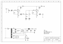
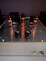
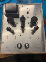
Should I rebuild this properly? The bias ports and knobs are kind of ugly but this was a test chassis that worked so well I still use it. The output stage is a single ended depletion MOSFET (IXTH6N50D2?) source follower loaded with the light bulbs inspired by Nelson Pass. The B+ (for the MOSFET stage) is about 65V loaded, the MOSFETs have 25V and 2A across them. No gNFB. 6N8S (in this case) driving a 6P3S with a 5k load (or 6L6 but I didn't have one) driving the source follower. Speakers coupled by the KEMET caps on the front which work so well I show them proudly 🙂
The B+ for the tubes is about 280V and comes from a boost converter. !@V SMPS supplies the heaters, boost, "logic" etc.

The B+ for the tubes is about 280V and comes from a boost converter. !@V SMPS supplies the heaters, boost, "logic" etc.
Last edited:

This is my creation from a YouTube channel by Robert Zovko. A class A SE tube amp with KT-88. 7-9W output power. Enough to drive sensitive speakers. For the time being it drives some Seas Mimir self made speakers and it sound wonderful.
Attachments
-
 tempImageLAuFjf.gif1.4 MB · Views: 263
 -
 tempImageb1r9e9.gif1.7 MB · Views: 209
 -
 tempImageuN8v2Z.gif1.4 MB · Views: 197
 -
 tempImageZ4CVaQ.gif1.5 MB · Views: 198
 -
 tempImageEFMdi0.gif1.5 MB · Views: 193
 -
 tempImageS6RDIX.gif1.6 MB · Views: 198
 -
 tempImages8GQD7.gif1.4 MB · Views: 197
 -
 tempImageCOguhC.gif1.3 MB · Views: 201
 -
 tempImageaLiN4d.gif1.5 MB · Views: 199
 -
 tempImageI8nDu0.gif1.4 MB · Views: 188
 -
 tempImageLHLNin.gif1.4 MB · Views: 199
 -
 tempImagegkBzUb.gif1.3 MB · Views: 209
 -
 tempImager7AQOY.gif1.6 MB · Views: 207
 -
 tempImageWUneJz.gif1.5 MB · Views: 214
 -
 tempImagelqWapq.gif1.4 MB · Views: 220
 -
 tempImageYQb3pF.gif1.7 MB · Views: 215
 -
 tempImageQRtmkt.gif1.8 MB · Views: 223
 -
 tempImageOPn8No.gif1.6 MB · Views: 254
 -
 tempImageygpAkH.gif1.4 MB · Views: 270
 -
 tempImageNCCkfB.gif1.5 MB · Views: 275
And some more pictures.
Attachments
-
 tempImagef5QqGJ.gif1.5 MB · Views: 147
 -
 tempImagePDrsOL.gif1.3 MB · Views: 139
 -
 tempImagelhzfTn.gif1.2 MB · Views: 131
 -
 tempImagevbGqwy.gif164.2 KB · Views: 134
 -
 tempImage1Irbt3.gif1.5 MB · Views: 162
 -
 tempImagetnVkAm.gif1.5 MB · Views: 129
 -
 tempImagewRtcoE.gif1.5 MB · Views: 127
 -
 tempImagey2Sxb5.gif1.5 MB · Views: 125
 -
 tempImagemx9Tkj.gif1.5 MB · Views: 119
 -
 tempImageGcyV9W.gif1.3 MB · Views: 141
 -
 tempImageABQzA9.gif1.2 MB · Views: 122
 -
 tempImageNNIZom.gif164.2 KB · Views: 117
 -
 tempImageiETj7s.gif1.7 MB · Views: 109
 -
 tempImageJxytgU.gif1.5 MB · Views: 122
 -
 tempImageAH87jk.gif1.4 MB · Views: 141
 -
 tempImagevJKMAx.gif1.5 MB · Views: 159
Member
Joined 2009
Paid Member
Keep it intact, if you tear it don and rebuild and don’t like the sound you will feel sad. Build another copy if you must.Should I rebuild this properly? The bias ports and knobs are kind of ugly but this was a test chassis that worked so well I still use it. The output stage is a single ended depletion MOSFET (IXTH6N50D2?) source follower loaded with the light bulbs inspired by Nelson Pass. The B+ (for the MOSFET stage) is about 65V loaded, the MOSFETs have 25V and 2A across them. No gNFB. 6N8S (in this case) driving a 6P3S with a 5k load (or 6L6 but I didn't have one) driving the source follower. Speakers coupled by the KEMET caps on the front which work so well I show them proudly 🙂
The B+ for the tubes is about 280V and comes from a boost converter. !@V SMPS supplies the heaters, boost, "logic" etc.
View attachment 1097319
Are you listening to cKXM or Ici on that tuner?
Hello do you have a circuit diagram with voltages for this amp ? Just curious to see what’s different in your amp.And another picture of one of the best sounding and also the vey cheapest PP penthode amp I have ever build. Had cost me about $75,- and beats every EL34 amp I have ever heard. It's completely build with military dump material wich cost about nothing. I really don't know wat I did but I never managed to build a better sounding penthode amp, even with the same tubes, better transformers and a lot more expensive parts. Just lucky I guess. It's build fully hardwired with ultrashort signal path a'la gainclone (didn't know at the time of building) and the whole thing is getting HOT HOT HOT, very HOT, every part of it, but it still work after 8 years.
Thank you
I've some pretty average vintage audio gear I bought in the seventies, a Leak 2000 tuner/amp, a Philips 308 turntable, a Sharp RT 442 H cassette player and some Goodman's Havant speakers.
On a whim, nearly fifteen years ago, I bought this Rock-Ola 443 jukebox.
It was very scruffy, the graphics and the record card insert had faded to blue. as they all do. But it was working.
![!BfhIJLQ!Wk~$(KGrHqYH-C4Erf,h4!PcBLBn8HpTl!~~_12[1].jpg](https://www.diyaudio.com/community/attachments/bfhijlq-wk-kgrhqyh-c4erf-h4-pcblbn8hptl-_12-1-jpg.1099208/ "!BfhIJLQ!Wk~$(KGrHqYH-C4Erf,h4!PcBLBn8HpTl!~~_12[1].jpg")
I gave it a good clean and a lube job, managed to get a new old stock record card from Victory Glass in the USA and painstakingly made a new graphic from overlaid coloured and frosted A4 acetates. The chrome is in excellent condition, though a couple of bits of anodised trim could do with a buff up, and there's a scratch on the dome glass, but I can't be bothered. It's now 53 years old and plays well.
It, with a Rock-Ola 468 in nearly as good condition, live in our summerhouse at the bottom of our garden and provide music when I'm working in it.
On a whim, nearly fifteen years ago, I bought this Rock-Ola 443 jukebox.
It was very scruffy, the graphics and the record card insert had faded to blue. as they all do. But it was working.
I gave it a good clean and a lube job, managed to get a new old stock record card from Victory Glass in the USA and painstakingly made a new graphic from overlaid coloured and frosted A4 acetates. The chrome is in excellent condition, though a couple of bits of anodised trim could do with a buff up, and there's a scratch on the dome glass, but I can't be bothered. It's now 53 years old and plays well.
It, with a Rock-Ola 468 in nearly as good condition, live in our summerhouse at the bottom of our garden and provide music when I'm working in it.
Very nice! I like the details like the cooling holes under the resistors, the high voltage slots around the level control and the holes adjacent to the anodes and screens. I look forward to seeing the finished product.Work in progress, PP KT120 HI-END class A .🙂
- Home
- Amplifiers
- Tubes / Valves
- Photo Gallery