hello again:
I have been in the shop listening to it all day. It has settled in very nicely. I think it sounds very good on the cheap, dusty Sansui speakers I have in the shop. Right now I think it is cleaner and more evenly balanced than my 6sn7 aikido -> F4.
So far everyone that have seen and heard it seem to smile. So that is good.
It clips before I get full open, at about 9 on the dial with the shop CD player.
Next is to test it out with my friends phone to see how it sounds with a 1.3 V signal. I may put a voltage divider on one of the inputs to deal with the over powering CD player depending on the listening session when it comes upstairs.
Thanks for the comments

hello 6A3sUmmer:
This amp was primarily made as a gift for a good buddy. He is a practical guy and a bit of a cogs and gears fellow. I wanted something out of the ordinary for him. I got it from a 3D printer accessory and development site. Not bad for $3.00cdn. It took a minor amount of modification to make it work. I will use the idea again.
The clean top plate was challenging to achieve I actually did the complete build twice to make sure everything was in the right place. It is something that really stands out for me. It gives it a much more refined presentation.
Glad you like my work.
Thanks for the nice comments
I completed another tube amplifier, a successful project with the help of my friends, Tirla Daniel, Daniel Sendre, Audiocris Amplifiers, with my thanks. Probably, it is the best amplifier, built by me, until now. Sunshine amplifier, the best.


Last edited:
Those shields are quite unique-DH Pentodes RIAA in testing with power suplyView attachment 1114882View attachment 1114881
Like something you'd see a bartender use... 'shaken, not stirred'
Very refined as usual, Alex... kudosI completed another tube amplifier, a successful project with the help of my friends, Tirla Daniel, Daniel Sendre, Audiocris Amplifiers, with my thanks. Probably, it is the best amplifier, built by me, until now. Sunshine amplifier, the best.View attachment 1115224View attachment 1115225View attachment 1115228View attachment 1115229View attachment 1115230View attachment 1115231View attachment 1115232View attachment 1115233View attachment 1115234View attachment 1115235View attachment 1115237View attachment 1115238View attachment 1115239
Jim
The DHP are millitary from radio trransmiters battery powered. Heaters run at 2.2 v 0.15 a and 0.2 aThose shields are quite unique-
Like something you'd see a bartender use... 'shaken, not stirred'
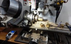
Looks like a pair of Bud brand utility boxes? What was the advantage to building them upside down?Facebook says I posted this pic 11 years ago.
It was a headphone amplifier and it's long gone.
View attachment 1119614
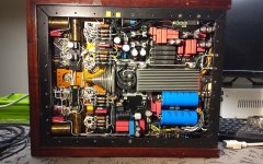
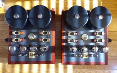
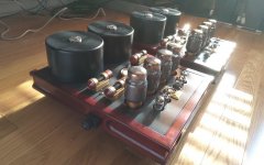
One of my more conservative builds.
Sonic Frontiers Power II
More here.
https://www.diyaudio.com/community/threads/need-help-on-a-diy-sonic-frontiers-power-ii.391689/

Sonic Frontiers Power II
More here.
https://www.diyaudio.com/community/threads/need-help-on-a-diy-sonic-frontiers-power-ii.391689/
Attachments
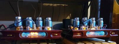
I bet others are wondering too: what are the 4 rocket-shaped objects between the output tubes and transformers? BTW very eccentric build - I'ld love to see some of your less conventional amps...One of my more conservative builds.
Sonic Frontiers Power II
More here.
https://www.diyaudio.com/community/threads/need-help-on-a-diy-sonic-frontiers-power-ii.391689/
View attachment 1120787
I kind of thought they looked like superchargers... They are in fact precision resistors that control the negative bias. There is a small 3-way switch between them to select which valve to monitor on the meter. It's fast, easy, and can be done on the fly.
The preamp for these can be found here.
https://www.diyaudio.com/community/threads/photo-gallery.71300/page-543
;Glenn
The preamp for these can be found here.
https://www.diyaudio.com/community/threads/photo-gallery.71300/page-543
;Glenn
Attachments
My first amplifier project!
This is one step shy of complete (twisting the transformer primary leads and secondary grounds). I didn't get a photo of the finished project, and the effort required for the difference...

Closeup of the amplifier section itself.

Walnut sides are french polished with garnet shellac. I made them with my two year old daughter; no power tools. Chassis is inset into the scales by about a third to half their depth.

Glowshot.

Sounds fantastic! It's replacing a $14 Pyle preamp from Amazon. It got the job done, but obviously lots of room for improvement. Next step is a matching line amp and speakers!
This is one step shy of complete (twisting the transformer primary leads and secondary grounds). I didn't get a photo of the finished project, and the effort required for the difference...
Closeup of the amplifier section itself.
Walnut sides are french polished with garnet shellac. I made them with my two year old daughter; no power tools. Chassis is inset into the scales by about a third to half their depth.
Glowshot.
Sounds fantastic! It's replacing a $14 Pyle preamp from Amazon. It got the job done, but obviously lots of room for improvement. Next step is a matching line amp and speakers!
- Home
- Amplifiers
- Tubes / Valves
- Photo Gallery