Hello Koda:
I am in the same boat. This hobby takes as much time to organize the bits and pieces as it does to build interesting projects. I seem to struggle with finding items in the "store" room. Which is a large stack of poorly labeled boxes. There has to be a better way!
All the best
I am in the same boat. This hobby takes as much time to organize the bits and pieces as it does to build interesting projects. I seem to struggle with finding items in the "store" room. Which is a large stack of poorly labeled boxes. There has to be a better way!
All the best

Since the 4 seasons in Canada are June, July, August, and Winter... You've got plenty of time indoors to sort those out before it's 🚴♂️ weather again-lol
So 90 minutes and the battery was 10.2V... Time to charge the little POS. No perceivable difference in sound though.
Not tubes, but has this happened to you lately?
So annoying!
I had a worse experience. I needed to reset my office switch. Needed a "pokey thing". Picked up a paper clip off a shelf and bent it open.
The damn paper clip was chrome plated and little slivers of chrome pinged off the paper clip in all directions... all over my breadboard. Too me ages to be sure there were no more.... found another one yesterday in a breadboard hole!
I am delligent about keeping cuttings and discarded component leads at bay. Having little bits of metal shavings in a computer/electronics lab is not cool!
I have spotted an SLA battery with no blade fuse.Testing the new headphone amp build but I can't find the stupid 12V 10A brick...
View attachment 1135713
View attachment 1135715
At least my identical battery has indeed got a blade fuse in a little housing with a press on cover.
No fuse? There's 4 feet of cheap wire connecting it to the amp... Call it a fuseable link!
It's designed to jump start a car... Fuse would be useless in that case anyway.
It's designed to jump start a car... Fuse would be useless in that case anyway.
Mine are being used mostly for general portable things. I bypass the fuse with jump leads if I start a car with one.
A new battery made the car much easier to start.
A new battery made the car much easier to start.
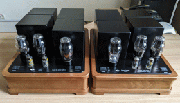
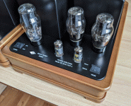
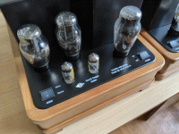
My two Amps:
E83F in triode mode with LED bias driving EL34 in triode mode, B+ is a little low so it only makes around 2W.
LND150 mosfet driving 2x EL84 in parallel, pentode mode with plate to cathode feedback. Good for 8W.


E83F in triode mode with LED bias driving EL34 in triode mode, B+ is a little low so it only makes around 2W.
LND150 mosfet driving 2x EL84 in parallel, pentode mode with plate to cathode feedback. Good for 8W.
disso,
Great looking amplifiers.
I design and build amplifiers that only output 2 to 6 Watts.
I do not need more power.
Now, all 5 of my amplifiers are either push pull; self inverting push pull; or balanced.
Two use Ultra Linear; one self inverting uses true triodes; two use Triode Wired Beam Power tubes (one self inverting, one balanced).
No negative feedback except the local negative feedback of:
Ultra Linear: Ultra Linear screen taps;
Balanced: A common self bias resistor for the cathode to cathode connection of the driver tubes; and a common self bias resistor for the cathode to cathode connection of the output tubes.
(oops, I broke my rules for individual self bias resistors; but now I do not need bypass caps across the common self bias resistors; I just have to be sure the tubes are very well matched).
Happy Listening Everybody!
Thank you!
You are right, 2W are more than enough for my office/lab. my speakers are quite efficient as well so i'll never need 8W, good to have the headroom tho.
So far i have only built SE designs but i definitely want to give PP a try, a friend of mine may need a bass guitar amp in the future and he asked me if i could build something with tubes. Thinking 4x6L6GC to extract 80-100W.
I was also thinking about building a PP amp for myself with 6AS7/6N13S or even GU50, but the matching of output tubes will be an issue here. I'll probably use fixed bias adjustable for each pair of tubes.
I have experimented with different feedback arrangements on the EL34 amp, plate to plate/schade, global and plate to cathode. In the end i prefered having no feedback here. On the EL84 i just picked this because it was easy to implement (i made PCBs for this amp) and simulated well. afterwards i read that this arrangement may cause bad PSRR which would explain the small amount of hum, the amp still sounds great tho.
Last edited:
Hi together, yet another phono preamp. Nothing special, EF86 and double triode, passive equalization. I use JJ EF806S goldpin and 6N2П-ЕВ. However, I designed the PCB in a way that also a ordinary 12AX7 etc. would work. PCB's designed with KiCad. All the milling-engraving done with cheap chinese desktop-CNC. Verneer is american cherry tree, finish is just oil. Maybe I'll create another enclosure with reduced height but for now I'm fine with the result (given the limited DIY possibilities). BR Sven


Sven for someone with limited possibilities it's still very well done, congrats !
I see you power the filaments with DC. Any reason why you cabled it instead of lying it down on the PCB ? Maybe to allow for AC as well ?
I see you power the filaments with DC. Any reason why you cabled it instead of lying it down on the PCB ? Maybe to allow for AC as well ?
Initially the heaters were all AC. That would still work fine with 6N2P or similar (12AX7). However, with the 6N1P it required DC heating as there was too much hum which I couldn't neutralize enough with hampot. Therefore I switched to DC and it remain there. Had to revert back to 6N2P anyway, 6N1P needs double heater current. On the long run that would overload the transformer. But beside of that, I always would try to keep the heater traces on PCB as short as possible, since they have to be much wider and waste space.
Here's a pic showing the power supply with AC heater (humpot is at the back of the chassis). PCB were first revision, not usable in that chassis because of long leads.

Here's a pic showing the power supply with AC heater (humpot is at the back of the chassis). PCB were first revision, not usable in that chassis because of long leads.
- Home
- Amplifiers
- Tubes / Valves
- Photo Gallery