Substituting Ultem sheet for the top plates would fix that... clear, yellow tinted like shooter's glasses.Speaking about guts, I have never seen so much eye for detail, a shame that the insides are tucked away. Stunning..
I used Ultem polyetherimide for transparent lenses in automotive valve cover apps. Continuous heat resistance to 340*F. Never a prob...
Can be cut by hand, but cnc router or laser/water jet much easier. Rigid stuff... 3/16" could support those trafo's
Jim
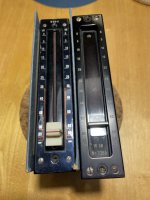
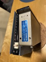
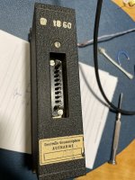
Very good find indeed, they were NOS (new old stock).


Last edited:

Looks like the European equivalent to a Daven pot, widely used in early NA studio equipment.
I assume that it produces 5 or 6 Watt.
Nice project !
Leaving the OPT out of the feedback loop is avoiding phase issues and makes the loop shorter. Naturally it will not be able to remidy any transformer limitations.
Nice project !
Leaving the OPT out of the feedback loop is avoiding phase issues and makes the loop shorter. Naturally it will not be able to remidy any transformer limitations.
Thanks Lampie519.
I haven't measured anything other than DC voltages since the prototype stage (before changing to tube rectifiers) but the output power should be around 3-4W. The output power is limited by the smallish power transformer, but on the other hand the tubes should last forever as they run at just over 15W Pdiss.
The feedback arrangement seems to work well, although there's only 2,5dB of CFB and another 6dB of plate to cathode feedback. The way I see it, both feedback loops works on tricking the output tubes to behave more like low mu triodes. Philosophically speaking, that is...
What i do somtimes is to add the secondairy of the OPT’s in the cathode circuit of the power tubes. No high dc voltages are to be expected by doing so as these windings are only a few Ohms. In this case the winding must be connected to ground on 1 side and phase need to be checked not to start an oscillation.
If this is too much work you also could try feed forward ( bootstrap) from the primary of the OPT to the anodes of the driver stage. Together with the feedback it should stay stable but gives extra “air” to the amp.
If this is too much work you also could try feed forward ( bootstrap) from the primary of the OPT to the anodes of the driver stage. Together with the feedback it should stay stable but gives extra “air” to the amp.
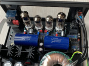
Hey, recently I've finished my upgraded version of OTL headamp. Very tweaked (I think 6th?) version to incorporate big foil output caps and 6N6P tubes. Includes regulated high voltage psu, current regulated series filament psu, full DC protection with turn on delay + status signalling. Contains not only phones output, but also line-out at rear panel to feed power amp + remote turn on +12V signal.
It is very small and fully covered for safe operation, managed to fit it into 22x19x9cm
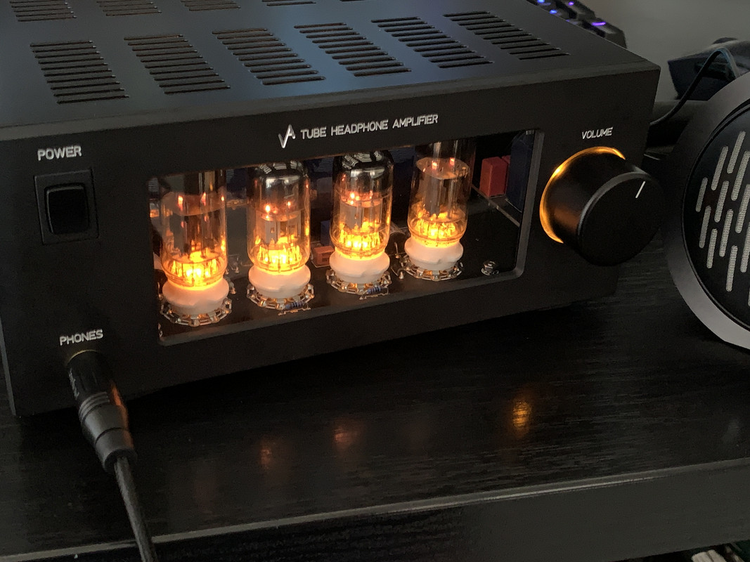
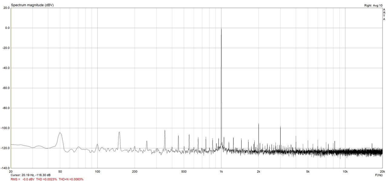
measurement 1Vrms@250R:
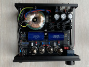
internals:

It is very small and fully covered for safe operation, managed to fit it into 22x19x9cm
measurement 1Vrms@250R:
internals:
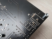
Not meant to nitpik, but pin 14 of your cmos chip looks like possibly didnt get soldered, or is light on solder-
Don't want problem to crop up due to it, especially if its part of your time delay turn on circuit.
Jim
Don't want problem to crop up due to it, especially if its part of your time delay turn on circuit.
Jim
what sharp eye you have 😀 truly from top it looks as it looks, but all good from bottom side, I suppose no need every single pad to fully flow thru... bottom:
Last edited:
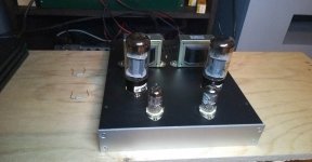
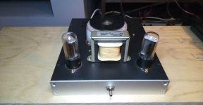
My first P2P tube PP amplifier built .


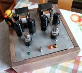
Yet another practice amplifier: EL34-SE inspired by the circuit published by Claus Byrith. However, I added some loudness control and use a 6SL7 instead of ECC83. I even tried with 6SN7, however it was lacking "something" (dunno what, but the 6SL7 version sounds better to me). Had the transformaer already available I decided for tube rectifier. Started with turret-boards, but switched to solder lug later since I find it too complicated exchanging parts in turret boards. For the top of chassis, I printed badges from drawings and then did the metal work. This could be one of my favorite ideas at all in diy 😀 For safety reasons, all my builds nee to go in sealed enclosures. This one is again done from MDF with some verneer and just oiled finish. Faceplate is not diy this time (too big for my CNC) but ordered at Schaeffer. A window from brown acryl allows to see the tubes anyway. Unfortunately, this build is a little too big. Chances are high that I either dismantle or sell it sooner or later, building another, more compact one. Until then I wil enjoy listening to that guy because it does a great job (had already built a protoype of the Byrith circuit and was impressed).


Preparing for the annual HIFI/DIY meeting in Sweden I decided to have a look at an abandoned project, the "Dynaco" 10W 6V6-PP amp that I hade safely stored in the basement. It was built on a PCB from eBay or AliX and I remember that when I tested it the first time there were "issues", so I let it "age for a few years", hoping time would deal with the problems.
Well, now I found out I had full volume independent of potentiometer setting and it was howling. Well, I found only tubes for one channel and had to order another set from Germany, but found the missing set while looking for something else.
Replacing the potentiometer and swapping wires to the OP tranny fixed all problems, but I should maybe have a look at what modifications are recommended. Swapped the ugly volume knob.
Now on the bench a 12B4A with a HV DC/DC SMPS. This one makes crazy as I cannot find a schematic that seems to fit with the build.
Attachments
Sven79,
That is a very nice looking amplifier.
EL34 single ended stereo amplifiers do sound great (I designed and built one years ago).
The schematic has a volume control, a tone control, and a negative feedback control.
Your picture shows the front panel with a volume control, a loudness control (the tone control?), an input selector; and the top panel with another control (negative feedback control?).
Is my guess correct?
Thanks!
soundbrigade,
If your "Dynaco" 6V6-PP 10 Watt amplifier is the same as the schematic I have seen many times before, then . . .
I do not think there are any real improvements possible other than using the best output transformers you can find.
The reason I think that is because that circuit is what some call 'Positive Synergy'.
That is where the performance results are better than the simple sum of the parts.
Just my opinions.
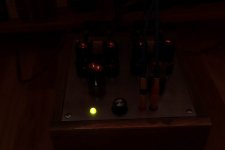
Since I am in Oregon, if I saw an amplifier with a Yellow Duck, and a Green Pilot light, I would guess it was produced by the University of Oregon.
I went to Oregon State, so it just a joke on U of O, not a joke on you.
Your amplifier looks better than my amplifiers do.
Keep up the good work.
If your "Dynaco" 6V6-PP 10 Watt amplifier is the same as the schematic I have seen many times before, then . . .
I do not think there are any real improvements possible other than using the best output transformers you can find.
The reason I think that is because that circuit is what some call 'Positive Synergy'.
That is where the performance results are better than the simple sum of the parts.
Just my opinions.
Since I am in Oregon, if I saw an amplifier with a Yellow Duck, and a Green Pilot light, I would guess it was produced by the University of Oregon.
I went to Oregon State, so it just a joke on U of O, not a joke on you.
Your amplifier looks better than my amplifiers do.
Keep up the good work.
- Home
- Amplifiers
- Tubes / Valves
- Photo Gallery