just curiosity for how it all works so no real specific questions")
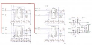
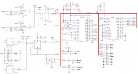
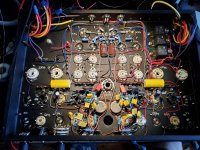
Finished cleaning up the schematics and here is how the analog part looks like. Everything is pretty much the textbook implementation. But the simplicity of a transformer coupled circuit was definitely the attraction here.
Attachments
Member
Joined 2009
Paid Member
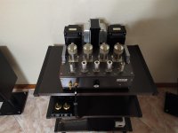
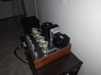
Had to find out how the new materials for labelling are working so re-did the front and back panels for the power amplifier. Also, in light of PP amplifier coming, it needed a SE in the name. A friend commented that they look swanky
Swanky !
Had to find out how the new materials for labelling are working so re-did the front and back panels for the power amplifier. Also, in light of PP amplifier coming, it needed a SE in the name. A friend commented that they look swanky
This is a beautiful color concept....
My second project
Hello everybody,old follower first post atempt here.
My litlle soundblaster;
GU50 PP UL 2x50 w rms.
Hello everybody,old follower first post atempt here.
My litlle soundblaster;
GU50 PP UL 2x50 w rms.
Attachments
Nice amps Radiola, I too am enamoured of the colour scheme. Finishing amps is a bugg*r. Just done a chassis for an amp, screwed up, drilled a few holes where I shouldn't. Filled em in, could I get it right, could I bugg*ry. Tried several times. Painted it, looked crap, could still see blemishes. Started all over again. Carefull with that drill Eugene.
Nice looking amp too Alex, you design the board yourself? Not of a fan of PCB's with valves, too much heat, still, it keeps things tidy, quick to build too.
Another corker of the amp builders art, oh Greek member with an unpronounceable name. Busy indeed, does it hum?
Looking good Koda, I notice you too like using blue 1% resistors, why? Valves are far from precise so why precision R's? Apart from they look nice. Curious.
Andy.
Last edited:
Yes is busy indeed but is dead quiet.oh Greek member with an unpronounceable name. Busy indeed, does it hum?
Andy.
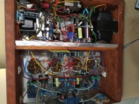
Compine star and bar ground, 100% success.
Hello everybody,old follower first post atempt here.
My litlle soundblaster;
GU50 PP UL 2x50 w rms.
UL? What is your B+?
415v B+ 5.5Kpp load, autobias control,UL? What is your B+?
<1% THD 2X35W, <2,8 THD 2X54W 8Ω.
Not count as hi-end device, but the sound is amazing.
Huge devastating bass delivery like mosfet amp witth 700va pt and
100000μF capacitor bank.
The low end of this is unbeilevable for tube amp.
The issue with screen voltage has reported and analyzed in this forum in the past.
I prefer to use MF types over carbon, and they're cheaper. I think I paid about 1 cent each for them (I bought 6000 in bulk).Looking good Koda, I notice you too like using blue 1% resistors, why? Valves are far from precise so why precision R's? Apart from they look nice. Curious.
Andy.
Thanks to all of the enouraging comments!
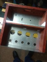
I started doing much fewer mistakes with drilling, which is all done manually in my case including some basic manual aluminum milling, when I switched to creating the drilling maps using the same software that I use for PCB routing. This way the actual circuit PCB could be imported into a design as a component and fairly precise placements could be executed. For example, the TOSLINK receivers in that DAC design got a mounting hole for a self-tapping screw. It ended up being aligned with drilled hole with maybe a quarter of a millimeter accuracy.
Just done a chassis for an amp, screwed up, drilled a few holes where I shouldn't.
I started doing much fewer mistakes with drilling, which is all done manually in my case including some basic manual aluminum milling, when I switched to creating the drilling maps using the same software that I use for PCB routing. This way the actual circuit PCB could be imported into a design as a component and fairly precise placements could be executed. For example, the TOSLINK receivers in that DAC design got a mounting hole for a self-tapping screw. It ended up being aligned with drilled hole with maybe a quarter of a millimeter accuracy.
"I prefer to use MF types over carbon, and they're cheaper." With you there, I too use what's to hand, bought a few hundred 1% 3w MF R's a few years ago, running out now, will bear this buying in bulk in mind when I re-order.
Pre-prepared drill plan and quarter on a mil accuracy, wow. I'm a more wing it and drill by hand kind of chap, I never have a layout 100% planned & hate PC programs but it does result in less mistakes I guess.
Andy.
Pre-prepared drill plan and quarter on a mil accuracy, wow. I'm a more wing it and drill by hand kind of chap, I never have a layout 100% planned & hate PC programs but it does result in less mistakes I guess.
Andy.


- Home
- Amplifiers
- Tubes / Valves
- Photo Gallery