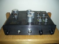
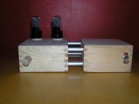
SY said:Is that an optical illusion or do you have the ground lead screwed into the wood?😉
I think that complies fully with code Sy! Ground terminal bolted to case, not soldered. 😀
" ... Is that an optical illusion or do you have the ground lead screwed into the wood? ..."
Actually, depending on conditions its not a bad idea: it keeps that pesky lead from flopping around inside the case, it allows an easy test point for taking meter readings (inside and from the outside through bolt) while hunting for any ground loops, and if the wood (MDF?) is wet from spilled beer or whatever it may actually establish a high impedence ground to the case.

Actually, depending on conditions its not a bad idea: it keeps that pesky lead from flopping around inside the case, it allows an easy test point for taking meter readings (inside and from the outside through bolt) while hunting for any ground loops, and if the wood (MDF?) is wet from spilled beer or whatever it may actually establish a high impedence ground to the case.
hahaha yea, It was just a left over from the power socket, and thought... meh who needs an earth 😉 and didn't want it flapping around 
I will be putting it in a metal case at some point, maybe over the christmas break, maybe leave it as is and just get some metal paint spray cans and give it a few coats 🙂
I will be putting it in a metal case at some point, maybe over the christmas break, maybe leave it as is and just get some metal paint spray cans and give it a few coats 🙂
Aikido-based linestage
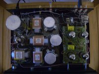
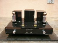
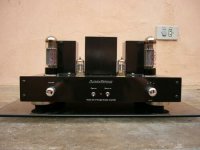
Here's my Aikdio-based linestage, using Bas's boards. All 6SN7s.
I mounted the boards, rectifier, and the big ASC caps on 2" ceramic standoffs, so they poke out the top. And the selector and volume pot are mounted at the back near the inputs.
I still need to make an adequate cover...right now I am just using a sheet of perforated aluminum from Home Depot. The chassis itself is cannabalized from an old Golden Tube Audio preamp...I have the original cover, but no way currently to cut the required holes in 12 gauge steel.
I'm also thinking about making a brand-new cover...and painting it dark red like the Cary Audio preamps...I love that look...
Attachments
Bas Horneman said:Wow Jayme. Impressive build! How do you like the sound?
Thanks...this was my first DIY build.
The sound? Quite simply....amazing. The clarity is better than anything I've heard, and frankly I didn't know my speakers could reproduce bass that low. It's definately a reference piece in my system. The Aikido topology really does remove a lot of distortion and coloration from the linestage...
The bad thing is I now know just how poorly recorded most of my CDs are...time to finally get a turntable.
I've got AC on the heaters, with zero noise and hum.
I used teflon CAT-5 for all of the B+ and Signal wiring, other than the ground wires.
jayme: " ... The bad thing is I now know just how poorly recorded most of my CDs are...time to finally get a turntable. ..."
Very impressive "hardware hack" = sourcing "cannabalized" chassis and other parts. (You may eventually have some galvanic interaction between the steel chassis and your aluminum grid work ... maybe not.)
Is it possible for you to evaluate a 96k or 192k DVD-A instead of your current CD player / discs? I have just started exploring this area and the results are amazingly better than 44/48k CDs ... almost as good as vinyl ... almost.
" ... I've got AC on the heaters, with zero noise and hum. I used teflon CAT-5 for all of the B+ and Signal wiring, other than the ground wires. ..."
Got scimatics or wiring diagram ? Interested to see your approach to hum & noise removal.
"ALL" The noise and a posible hum is very hard to remove.
Mybe on 85-90 db speakers you not have "any" noise.
You should see on 96-100 db spl speakers and tell us please.
Mybe on 85-90 db speakers you not have "any" noise.
You should see on 96-100 db spl speakers and tell us please.
Re: Frank's line pre
Interesting design idea. That toggle switch has to go!
How about a pair of 6ax4 octal damper tube diodes on the power supply to balance the esthetics, similar size to 6SN7.
yagoolar said:My approach to building Frank's line pre based on russian 6H8C. No finished yet, but...
Interesting design idea. That toggle switch has to go!
How about a pair of 6ax4 octal damper tube diodes on the power supply to balance the esthetics, similar size to 6SN7.
Re: Re: Frank's line pre
Do you mean to get rid of the switch?
And yes, I was thinking about tube rectifiers. Actually, russian 5U4C (lat. 5c4s) are similar to 6H8C in size. I will re-think the idea. Thanks.
rcavictim said:
Interesting design idea. That toggle switch has to go!
How about a pair of 6ax4 octal damper tube diodes on the power supply to balance the esthetics, similar size to 6SN7.
Do you mean to get rid of the switch?
And yes, I was thinking about tube rectifiers. Actually, russian 5U4C (lat. 5c4s) are similar to 6H8C in size. I will re-think the idea. Thanks.
Re: Re: Re: Frank's line pre
I think he means that it is not aesthetically pleasing.
yagoolar said:Do you mean to get rid of the switch?
I think he means that it is not aesthetically pleasing.
Latest project up and running. 🙂
This is a four channel OTL. The input tube is 6C45, phase splitter and drivers are 6H6 and the power tubes are six PL519 per channel. News is that PL519 is in "enhanced triode" mode, i.e an extra positive voltage referring to the anode (30 volt in this application) is connected to the screen grid. I do not know of anyone building an OTL this way before.
An externally hosted image should be here but it was not working when we last tested it.
This is a four channel OTL. The input tube is 6C45, phase splitter and drivers are 6H6 and the power tubes are six PL519 per channel. News is that PL519 is in "enhanced triode" mode, i.e an extra positive voltage referring to the anode (30 volt in this application) is connected to the screen grid. I do not know of anyone building an OTL this way before.

- Home
- Amplifiers
- Tubes / Valves
- Photo Gallery