Beautiful work.Point to point soldering which is beautifully done.

It is great to see a man using tools driven by "breadengine"Only this photo at the moment. I'll update it when I take more.
View attachment 1345090
Here's a pic of my CNC machine, it runs on beer and hotdogs...😉
View attachment 1345093
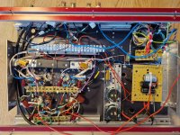
I built this 12b4a preamp based on Eli's schematic with Ale's gyrator.


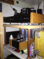
Amplifiers made by me on 300B tubes. Monoblocks and stereo versions.


Last edited by a moderator:
Here are my EL34 PP amps made years ago

Last edited by a moderator:
My first project..a Chinese 6P6P preamplifier kit. It came fairly complete and with the help of some kind folks here it sounds great!
I added a couple solid aluminum knobs, upgraded a few capacitors and an Alps volume pot, otherwise stock. I've been bitten. Pete Millett's Engineer's Amp going on the workbench 🙂


I added a couple solid aluminum knobs, upgraded a few capacitors and an Alps volume pot, otherwise stock. I've been bitten. Pete Millett's Engineer's Amp going on the workbench 🙂
Three chassis headphone amplifier I made featuring Slagle AVC, interstage transformers, and output transformers. This one has been in the works for a few years, intended to be my very last headphone amp. AVC is in separate chassis, as is the power supply to keep the noise floor low, and it is inaudible. All power supplies are regulated. Signal path goes AVC > LED biased parallel section 5687 / E182CC / 7044 input > 49% nickel interstage > fixed bias triode strapped HY69 output > 49% nickel output. Output transformers have high and low Z taps, 32ohm and 100ohm secondaries.
Thought about making a dedicated post about it, showing the innards, etc. but not sure if there would be interest.


Thought about making a dedicated post about it, showing the innards, etc. but not sure if there would be interest.
Nice work, yes make a thread with Circuit diagrams as well
A little preview of my latest amp: T20 SE class A2 with EL36 cathode follower drivers and 6AC7 input stages. Three different local feedback loops, no global feedback. More pics to come, the PSU is still on a breadboard.

Three chassis headphone amplifier I made featuring Slagle AVC, interstage transformers, and output transformers. This one has been in the works for a few years, intended to be my very last headphone amp. AVC is in separate chassis, as is the power supply to keep the noise floor low, and it is inaudible. All power supplies are regulated. Signal path goes AVC > LED biased parallel section 5687 / E182CC / 7044 input > 49% nickel interstage > fixed bias triode strapped HY69 output > 49% nickel output. Output transformers have high and low Z taps, 32ohm and 100ohm secondaries.
Thought about making a dedicated post about it, showing the innards, etc. but not sure if there would be interest.
View attachment 1358655
I am somewhat lost with avc connection - is it RCA? Normally you have input and output. By he way, what is the size of Slage OPT's?
My latest build is a dual mono balanced line stage.


I started this project several years ago, but ended up redesigning the main line stage circuitry several times (actually five 🙂) until I got something that sounded the way I wanted and better than my previous solid-state preamp. My final line stage design uses a pair of 6SN7s with the sections paralleled in a differential circuit. The anodes are connected through a Lundahl LL1660PP/NC transformer in 2.25+2.25:1 configuration.
The cathodes are connected through separate cascoded BJT current sinks, with a small resistor connecting the two. This allows me to get ideal DC balance and to reduce the gain a bit. I got this idea from Allen Wright (RIP) who used this approach in his later Vacuum State RTP3 designs. Overall gain is set to ~13db.
Each channel has its own custom Toroidy transformer (fed with a Neurochrome soft start) with a Schottky bridge rectifier and CRCRC filtering, which is then regulated using a Salas SSHV2 circuit. I had originally planned to use a Neurochrome Maida regulator, so I designed my own PCBs for the SSHV2 to be mechanically compatible with the Maida regulator.
The 6SN7s are biased to 14ma for the two parallel sections, and the regulator is set to 190V. I have a -12V supply for the bottom of the current sources.
Input selection and attenuation are done using AMB.org delta 1 & 2 boards in a balanced configuration. I splurged on exotic resistors (using Z-foils for series resistors and Audio Note silver tantalums for shunt resistors). While I really like the sound of these resistors, I don't think they are worth the added expense compared to Vishay-Dale RN series metal films. In future projects, I'll probably go with these, perhaps using a 2W silver tantalum for the final shunt resistor.
In addition to the tube line stage, I also have a pair of AMB-org alpha 24 boards for single ended outputs which I use for my subwoofers. This is powered by its own Neurochrome Preamp Power Supply which provides +/- 12V.
Control of the input selection and stepped attenuator is done with an Arduino with custom software, with a color TFT display. I also have an output relay which is engaged after the tubes have had time to warm up, and a 12V output trigger to turn on my power amps.
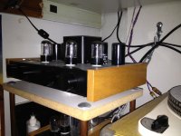
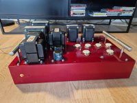
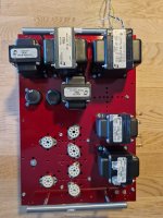
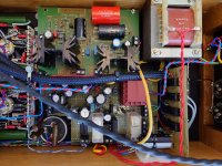
Then my copy of Dynaco's 6v6 pp amp starts to be finished. A little connection of B+, assembly of drop resistors, checking and testing. Lots of iron on this amp. A choke common to both channels, and one per channel after the big one,with capacitors in between! The amp probably weighs 25 kg..
Attachments
i know that replying to a 21 year old post may not be the best idea but do you have the schematic for it? it looks really intrestingLooks like I can claim the first post! Hmmm what to throw on the pile....
Hi,
Couple of years back i build me dad some monoblock kt88 pp power amps. Those where always meant to go with a pre. This spring I build it. The line stage of an RTP-5 as designed by Allen Wright. Was a nice birthday present to me dad i think . Sounds good, looks ok i think.


Couple of years back i build me dad some monoblock kt88 pp power amps. Those where always meant to go with a pre. This spring I build it. The line stage of an RTP-5 as designed by Allen Wright. Was a nice birthday present to me dad i think . Sounds good, looks ok i think.
Attachments

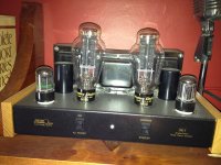
SE300B mono block amps I built in the mid 90s for my dearly departed friend, Steve Melkisethian of Angela Instruments
Did you build it or is it a bought amp? The manufacturers site doesn't give much info apart from the usual "lets flog an amp" with loads of subjective hyperbole, apologies, maybe being a tad cynical & grumpy: if you like the amp....
Re; swopping valves, to be honest I can't tell the difference between a NOS Mullard valve & a Zaerix. Same goes for a RCA 6SN7 & a Soviet 6H8C, but then my ears roll off at about 15khz on a good day. Whatever, have fun, enjoy listening listening to music.
Andy.
Re; swopping valves, to be honest I can't tell the difference between a NOS Mullard valve & a Zaerix. Same goes for a RCA 6SN7 & a Soviet 6H8C, but then my ears roll off at about 15khz on a good day. Whatever, have fun, enjoy listening listening to music.
Andy.
- Home
- Amplifiers
- Tubes / Valves
- Photo Gallery