Our person. (Наша людина, справжній фошист. ))) )What is the swastika about?
The swastika is an ancient Hindu symbol that denotes good luck or fortune and is used in that context.What is the swastika about?

It has nothing to do with Fascism, it's a Hindu religious symbol.Our person. (Наша людина, справжній фошист. ))) )
Our man, a real fascist.
Englih please
dave

diyAudio moderation team
Miu.miu,
That looks very nice!
Is that a current source plate load; plus a coupling cap and a non air gapped output transformer?
As always, posting a schematic is appreciated.
Decades ago, I went to Jakarta and Surabaya.
Interesting country; that was fun to see; good food too.
That looks very nice!
Is that a current source plate load; plus a coupling cap and a non air gapped output transformer?
As always, posting a schematic is appreciated.
Decades ago, I went to Jakarta and Surabaya.
Interesting country; that was fun to see; good food too.
Last edited:
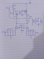
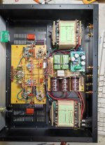
Hi, here my first finished tube power amplifier, parallel single ended with active loaded output stage
Great works. Your layout and how to solder the components together point to point are neat work. Fantastic, and this is one of the most beautiful works I've seen! Congratulations!!Hi, here my first finished tube power amplifier, parallel single ended with active loaded output stage
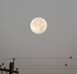
Could you have been playing some music at the time and the exposure randomly caught it on a high peak of a half-cycle? I ask because I have seen this on some modified MI-12188A amplifiers when square wave testing at 10Hz. Alternate pairs of 807s would give the glass glow and it was very pretty to see it flicker back and forth.An interesting night-time view of my double quad 6550 2x115W amp. A couple of tubes nicely have a very strong flourescent blue on the inner envelope, why don´t the others show the same when all tubes are well matched ? trace impurities ?
Bench Baron
Only this photo at the moment. I'll update it when I take more.Re the amp in post 11,639, have you any under chassis pics please? Someone must a CNC machine, I love the airhole design, never seen but still there.
Ali Om, Om Shiva, Andy.
Here's a pic of my CNC machine, it runs on beer and hotdogs...😉
- Home
- Amplifiers
- Tubes / Valves
- Photo Gallery