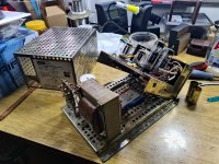
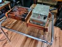
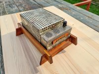
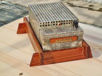
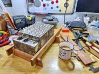
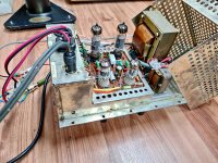
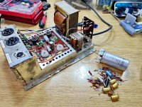
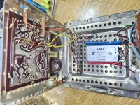
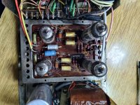
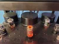
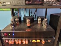
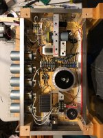
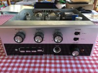
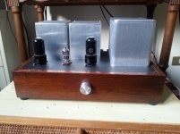
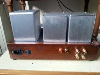
😛 recently got my hands on a Grundig NF1 chassis with valves still inside... changed all the resistors and capacitors, and removed the big can that was so dry it rattles, and had to put small 12V transformer in series with mains transformer primary to lower the voltage to 220V (sadly the mains transformer doesnt have a 230V winding, so this was a solution to avoid big resistors and added heat)... checked the voltages, all OK, got the filament voltage 6.4V 😀, and was surprised to measure 23mA per section on ELL80`s... it sounded so nice that I decided to make a docking station for it, and here it is - over 60 yrs old, and playing 😛... a Grundig NF1 tribute to, sortof 🙂
Attachments
-
 20211021_160202.jpg700.1 KB · Views: 812
 -
 20211110_133727.jpg663.6 KB · Views: 385
 -
 20211110_132853.jpg658.3 KB · Views: 354
 -
 20211110_132818.jpg646.5 KB · Views: 375
 -
 20211110_132721.jpg784.5 KB · Views: 399
 -
 20211107_172341.jpg715.5 KB · Views: 416
 -
 20211105_213340.jpg787 KB · Views: 763
 -
 20211104_200716.jpg783.7 KB · Views: 742
 -
 20211021_160827.jpg771.3 KB · Views: 794
 -
 20211021_160332.jpg703.1 KB · Views: 786
😛 recently got my hands on a Grundig NF1 chassis with valves still inside... changed all the resistors and capacitors, and removed the big can that was so dry it rattles, and had to put small 12V transformer in series with mains transformer primary to lower the voltage to 220V (sadly the mains transformer doesnt have a 230V winding, so this was a solution to avoid big resistors and added heat)... checked the voltages, all OK, got the filament voltage 6.4V 😀, and was surprised to measure 23mA per section on ELL80`s... it sounded so nice that I decided to make a docking station for it, and here it is - over 60 yrs old, and playing 😛... a Grundig NF1 tribute to, sortof 🙂
Just a word of warning, you should replace your rectifier bridge as they have a tendency to break it can then destroy your amplifier. Otherwise, it is a fun concept to use older tube amplifiers like this.
Really, really you did a great job pamook!
I admire your dedication to get this amplifier working again.
Respect!
Joe.
I admire your dedication to get this amplifier working again.
Respect!
Joe.
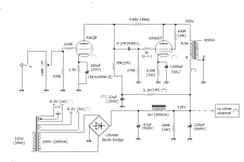
🙂 thank you ppl 😀.... and for selenium rectifier - yes, it will be removed in "second wave" 😉, just need to take care of voltage drop... this happened to be a pick from the local ads, and well deserved to play again... it has a very nice and soft sound, not hifi as we all agree on, but nice, very clear mid/high and well defined but not too deep bass... but as a allrounder for playing music in the background, surely make me turn my head toward the speakers every now and then, surprises me with clarity.... and it came with all the tubes, and I must say that two ECC83s were Telefunken 😛 so they instantly ended in the secure drawer, and some nice Siemens were put in. ELL80s are Lorenz, with almost full emission (whick also surprised me), I was ready to make a ELL80--> double EL95 adaptor but for now, no need.
Thx again for kind words, greatly appreciate it 😀
...great hobby, this is.... just great 😀
Thx again for kind words, greatly appreciate it 😀
...great hobby, this is.... just great 😀
My MA-1 - 12GT5 amp can be push pull at 30W or SE at 3W just by pulling a tube on each channel apparently 😀 ** For those tho are watching the "misbalance of toroidal output transformers", my interleave in in play here (two coils under the covers, two more in the chassis underneath) and there's a 60mA misbalance.
Yes the house is dusty. This is dust after 2 weeks. (they are building several new buildings within 50m of here and I have the window open)
Yes the house is dusty. This is dust after 2 weeks. (they are building several new buildings within 50m of here and I have the window open)
Attachments
Last edited:
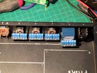
The start of a preamp... Metal work is tedious, but I think the layout works. I still need to make arrangements for my implementation of the 6E2 meter though. Magically, there's just enough space for them.
There was also a planned power failure today. I ran my lights, soldering iron, and my crapbox (6J1 buffer/tone (tone done by opamps) into cheap class D board) powered from a 7.2AH battery. After 2 hours, it was still 12.7V.
The "main" battery (the original eleven year old starting batter from my car) was at 12.4V with 30W of light and 60W of soldering iron here and there.
When I started charging it, the "smart" charger said it was at ~50% charge, gave it a max of 3.9A. When it was 70% or so, it ramped up to 5A. Smart indeed. On a good battery that's just been run down momentarily, it'll allow 14.9V@almost 20A (and the fan is loud 😀). It even has a 75A "crank" setting but I call bullship on that. Far too light to have a snowball's chance in hell at providing that kind of power with the flimsy TO220 parts inside IMHO... I could be wrong though - what if they were GaN?
Also, no. It's not perfect - RCA jacks are not aligned. But I hand crafted it without tools that plug in (Shoutout to DeWalt and Dremel for making decent tools - 15 years ago I would have vomited at the thought of a battery tool... Now? They kickass and take names.
It's also reall handy to have breakout boards for the pots... I made extras... 50 cents a piece plus mail is anyone needs any (blank board - no pot or connectors).
Why so many RCAs? Phono MM in, 3 line level source inputs, 3 line level source outputs, 3 variable outputs (for using more than one amplifier), 2 variable output transformer coupled outputs (for using amplifiers on other circuits to "break ground"...
The giant ugly holes will accommodate a pair of 250V 2200uF caps...
Attachments
Last edited:
Interesting project for sure! That's a lovely lot of inputs and outputs. Personally I'd ditch the breakout boards or use a different connector on them, because screw terminals can crush these delicate shielded wires breaking the contact.
Is the 1/4" jack on the front panel meant for headphones?
Oh, and the transformer-coupled outputs could be made balanced, with XLR or 1/4" jack connectors. Maybe it's just me, but I love professional audio 🙂
Is the 1/4" jack on the front panel meant for headphones?
Oh, and the transformer-coupled outputs could be made balanced, with XLR or 1/4" jack connectors. Maybe it's just me, but I love professional audio 🙂
I don't use delicate shielded wire - I just use RG174 and tin it,,,
Yes, the 1/4" jack on the front is the HP output.
I have XLR jacks to make it balanced, but I don't need it and RCA connectors take less space...
I still might try to add a A/D converter to get optical output.
Yes, the 1/4" jack on the front is the HP output.
I have XLR jacks to make it balanced, but I don't need it and RCA connectors take less space...
I still might try to add a A/D converter to get optical output.
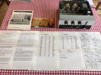
Rogers Cadet III Integrated Amplifier
Just found this beautiful, completely original, Rogers Cadet III Integrated Amplifier which is complete with all the original documentation.
It is completely original as supplied by Rogers back in the 1960's.
It is fitted with the gold PU Cartridge.
It had one owner from new who bought it from the local HiFi shop in Bedford, England. I purchased it from them. I have no wooden case (sleeve) as it was integrated into another piece of furniture.
I have all the original Rogers Documentation including Owners Manual, Rogers Brochure, Copies of reviews from 1960's publications. Documentation includes Circuit Diagram and a list of all the components and their values.
.
.
Attachments
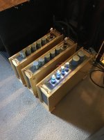
Hi all. Here's my second speaker tube amp made from wood around. For this I used a chestnut wood frame realized from an acquaintance carpenter, it is really nice and solid and I like the color nuances.
The amplifier is still like the first single ended, this time running with two 6V6gt tube and one 6AQ8. The voltage is lower and current too, so I can expect max. a 2.5W per channel. Notwithstandig the little power I can enjoy a quite round and detailed sound.
The amplifier is still like the first single ended, this time running with two 6V6gt tube and one 6AQ8. The voltage is lower and current too, so I can expect max. a 2.5W per channel. Notwithstandig the little power I can enjoy a quite round and detailed sound.
Attachments
- Home
- Amplifiers
- Tubes / Valves
- Photo Gallery