HV delay and Bluetooth, was the wish, of customer. I layout, a small PCB for this requirement . It work well, time adjusted to 40 seconds . Relay changed to SSR the blue one.
Nice work! I'd be interested in the delay schematic if you're prepared to post it. I just had to do something similar (Really soft HT start for DHT amp) but needed to use 2 relays because my customer didn't want a MOSFET in the HT.
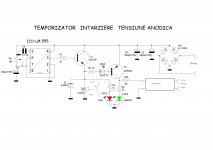
Thanks. My problem with a simple delay of 30s in the HT primary circuit was that when the relay activated there was some alarming excursion of the full-range speaker cone.
I'm sure something like this could be adapted by someone here with more knowledge of SS and MOSFETS?
Voltage Ramp - CircuitLab
Voltage Ramp - CircuitLab
Its feasible, however your mosfets are gonna be stressed hard if you do a slow warm up, need plenty of cooling, and if the timing capacitor develops leakage, your supply needs to be able to handle the increased dissipation.
Very interesting build. Looks good.Space is an interesting topic. I’ve chosen to eliminate the space a table/rack takes up. The inside pair are umbilical joined, the outer pair are mono blocks. There’s room for more 🙂
These chassis’s present around 550 square inches by 4 or 5 inches deep and I use it all. Lots of iron in my favored designs 🙂 Short signal path up top but the power supply is spread out some. I live away from the city so FM/ radio is no big deal. Amps are quiet.
Member
Joined 2009
Paid Member
Headphone amp for 1626 output tube using Bob Danielak’s classic “Darling” circuit, switchable with the later “Clementine” variant by inserting 8532 or 6SL7 input tube. Lundahl LL2765 OPTs, vintage PIO coupling caps, and carbon comp grid leak resistors contribute to its involving musical sound. I modified Bob’s design by employing a separate cathode network in each channel, rather than a common one shared by both. It sports a dual chassis of African padauk finished with Danish oil and lacquer. One shielded umbilical carries the 6.3V and 12.6V AC heater supplies while the other carries the HT voltage and signal ground; both carry the chassis ground via the shields and a conductor. I designed a power supply with the type 80 rectifier into a double pi filter with 10h chokes and oil-filled motor run caps. It’s only begun breaking in but sounds excellent so far. I listened to Radiohead’s “House of Cards” 4 or 5 times last night.
nicely done!
and that Jetsons post was looking good too!
801A A2 SET
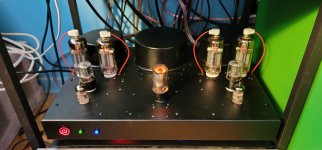
I finished an 801A A2 design the other day, I spent a lot of time and effort on it, very happy with the result. I posted pictures from the build in a dedicated thread, this is my favorite.

Here is the circuit.
 (1).jpg")
I finished an 801A A2 design the other day, I spent a lot of time and effort on it, very happy with the result. I posted pictures from the build in a dedicated thread, this is my favorite.
Here is the circuit.
Member
Joined 2009
Paid Member
I finished an 801A A2 design the other day, I spent a lot of time and effort on it, very happy with the result. I posted pictures from the build in a dedicated thread, this is my favorite.
View attachment 954259
Here is the circuit.
View attachment 954260
superb workmanship on that chassis, you clearly took a lot of care and insisted on quality, all the way down to the special volume knob, immaculate surface finish and the wiring to the top cap, perfectly cut holes, countersunk screws, everything just done right. Puts mine to shame.
Last edited:
Thank you! I cannot claim the workmanship on the chassis itself, that is outsourced to Dave at Landfall Systems who does excellent work, highly recommended. I designed the chassis and layout in CAD software, picked out the powder coat and shipped it, Dave did all of the hard work with the machining and coating.
Some time last year, I began powder coating chassis at home, which inspired him to buy some equipment. Now he is much better at it than me! Which is a relief, as it is a one stop shop for a high quality chassis, which I think is worth the price.
Some time last year, I began powder coating chassis at home, which inspired him to buy some equipment. Now he is much better at it than me! Which is a relief, as it is a one stop shop for a high quality chassis, which I think is worth the price.
I finished an 801A A2 design the other day, I spent a lot of time and effort on it, very happy with the result. I posted pictures from the build in a dedicated thread, this is my favorite.
View attachment 954259
Here is the circuit.
View attachment 954260
Wow, this looks really, really professional !
Very good job, even my wife would allow me place it in our
living room (yes, I did show her this picture).
Wow, this looks really, really professional !
Very good job, even my wife would allow me place it in our
living room (yes, I did show her this picture).
Haha! Thank you, I am honored to have her approval 🙂
Member
Joined 2009
Paid Member
I forgot to double check and ordered SSOP opamps.
Sorry to say, but that looks like the underside of somebodys running shoe 😱
I forgot to double check and ordered SSOP opamps.
Did you actually carve the PCB to embed the chip? I'm impressed you had the patience or dexterity to do that. It doesn't look "pretty", but it's also a super close up. I doubt I'd have been able to pull it off.
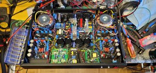
Another MA-1 is built. This one has safety interlocks AKA no B+ with C-...
Push pull trioded 6P36S for output (but since it's modular there are over 150 possibilities now) and my usual 6F12P/6N8S VA/PI/DR stage. SMPS for heaters and DC boost for bias supply. Also AB-4 for automatic bias. B+ 315V, 75mA idle. 2k2:6R loading.
Someone said they though the stacked toroids looked bad, so here a pair are hidden inside the chassis with the covers on top for once!
Attachments
Last edited:

- Home
- Amplifiers
- Tubes / Valves
- Photo Gallery