Hi Erik@56oval
I use Hamerite clear coat or Zapon Lack
The Zaponlck looks interesting . I use Incralac to coat copper ,adds a antique richness to the copper .
http://www.wattylindustrial.com.au/documents/industrial/tds/metal/Incralac v3.pdf
Attachments
Last edited:
Where should get them?
Bst RGRDS
Please tell us where could get this tips.I ran out of tip savers for my de-soldering tool and had to buy another bag of the things. 100 of them for the price of a tip that will last about the same amount of time as just one tip saver😀
Bst RGRDS
That's actually pretty interesting, I almost want to make one, but considering I only have about 5 CD's these days, it'd be sort of useless.
I've never owned one myself. Nowandays I rip my CD's (the music I cannot get in a higher resolution format) with RubyRipper and save it as FLAC files, which I can directly play with a DAC. This gives a lot of flexibility, as well as eliminating the issue of jitter (although a buffered SPDIF would eliminate jitter as well).
Hi
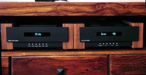
My new digital player.Music player CD-pro2 + DAC ESS9018 + USB Converter Xmos (Lucian)
Tube preamplifier 6n30p + SAC Transformers
CDpro2 Player DIY - YouTube
My new digital player.Music player CD-pro2 + DAC ESS9018 + USB Converter Xmos (Lucian)
Tube preamplifier 6n30p + SAC Transformers
CDpro2 Player DIY - YouTube
Attachments
Last edited by a moderator:
 Note: PNG is not a good format for posting photographs. Use Jpeg (.jpg) instead.
PNG is good for graphs and charts.
See here about posting photos.
http://www.diyaudio.com/forums/everything-else/183084-pictures-why-not-attach-them.html
I can go with that. Tube rec. for a CD player.
Yepp unbelievable but so true...tubes to sooth digital.😀..
You say in a cd player..but beware I am talking Transport Only here..(my dac is loaded with tubes)
" Only zeros and ones"....that sentence must come from non-listeners............
Tubes in the rectification circuit...once heard a clear nobrainer...

 ................................
Last edited:
Hi Erik
The Zaponlck looks interesting . I use Incralac to coat copper ,adds a antique richness to the copper .
http://www.wattylindustrial.com.au/documents/industrial/tds/metal/Incralac v3.pdf
Wonderful shot of your rig(s)....I simply love over the top...you are my man....

Wonderful shot of your rig(s)....I simply love over the top...you are my man....
Thanks mate ,all the best for Christmas
 Erik and the diyers
Cheers
Please tell us where could get this tips.
Bst RGRDS
What are those? Pieces of silicone tubing?
I haven't even owned a solder sucker for probably 20+ years. I just buy lots of desolder braid of various sizes 😀
They used to be used in test equipment before heat shrink became common and were also some industrial and cinema amplifiers in those days.
The part number on the bar code label should cross reference to a Newark part number as they come from there British agent for Newark.
H30X25 PINK - HELLERMANN TYTON - SLEEVING, 3MM, PINK, PK100 | Newark element14 US
That was easy wasn't it😀
There is also a fitting tool for them too.
Attachments
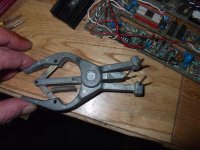
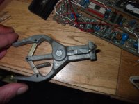
Thanks Sir for give a solution, the pliers, obviously, at least me, only for make a fast tracheotomy for put a laryngeal tube, but not for desoldering anything. The link, obviously is empty, but you show how the man's ingenious can help and how one pic can resume many words. Please accept my friendly regards for this Christmas time and please share with your friends and family the best auguries for the next year.
If the web link is empty perhaps have a quick look at your privacy software. I had to switch some of the privacy settings off in order to get Newark onto my screen.
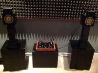
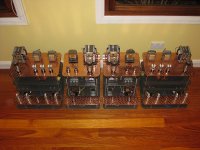
My second tube project. 4ch power amp.
"Test drive" in garage
Separate "power station" and 4x70w output.


"Test drive" in garage
Separate "power station" and 4x70w output.
Last edited:
My second tube project.
"Test drive" in garage
Separate "power station" and 4x70w output.
An externally hosted image should be here but it was not working when we last tested it.
Very nice. I can not help but think that when my house lights dim a little, someone has turned on one of these amplifiers somewhere in the world.
Are you going to put bells on the transformers? And what does the power side of things look like?
the power supply is quite boring.
Only three parallel-connected transformer, and bridge rectifier inside.
8-wire jumper cable and inside the amplifier enclosure is operating voltage filter and bias adjustments.
Maybe I build a transformer housings. I don't know yet.
Operating voltage are quite high. 485V.
I just studying on the internet rectifying tube structure.
It would lower the operating voltage and the power supply housing a better look.
Inside view
An externally hosted image should be here but it was not working when we last tested it.
Last edited:
My second tube project. 4ch power amp.
"Test drive" in garage
Looks to be EL34 driven by ECC83 (12AX7). The insides looks pretty complicated for a power amp. I would have thought you could have had room to fit the power supply inside the box. 🙂
...but it's 4 channels.
I really like the power supply separate, though it could have been smaller unless there's a lot of filter capacitors & chokes inside. Just the physical separation distance is a good thing.
Please don't degrade the performance just to be able to say it uses tube rectifiers.
I really like the power supply separate, though it could have been smaller unless there's a lot of filter capacitors & chokes inside. Just the physical separation distance is a good thing.
Please don't degrade the performance just to be able to say it uses tube rectifiers.
- Home
- Amplifiers
- Tubes / Valves
- Photo Gallery