Sweet thanks maxw for the suggestions, gives me something to play around with instead of starting from scratch on my on dual opamp design 🙂
Naz
Naz
To the beta-testers particularely,
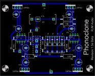
I worked on the layout a little to incorporate some of your suggestions.
1. Bigger resistors can be used. 12.5mm spacing, type 0309, which I take to be 1/2W. Of course smaller ones can be used in the space.
2. Optional use of a film output coupling cap. Model shows Wima MKP4 22.5mm lead spacing.
3. The RIAA caps shown are WIMA FKP2, Probably the MKP or MKS series are a better fit from a package dimension point of view, being thinner.
4. Bypass caps shown are Panasonic FC, 25V 100uF. Since I know many of you want to add more capacitance, I`ll see what can be done here. I was going to make the lead spacing 3.5mm on the input at least, but putting the metric component in my 0.1" grid was not pretty, so I left it for now.
5. While I dont think moving the regulators off the board is a good idea, it can easily be made an option, just by bridging the in and out voltage traces of the unused regulator socket holes.
6. After all that messing about, however, the board size is now 3 inches square. Choice doesn't come free...
Richard
Attachments
A couple of people have emailed me asking if PCBs are available.
The answer depends on the date you read this. I am taking orders until Saturday, April 30th, 2005. I will only have as many boards made as there are orders, so please don't email me later asking if any are left over because there wont be.
-R
The answer depends on the date you read this. I am taking orders until Saturday, April 30th, 2005. I will only have as many boards made as there are orders, so please don't email me later asking if any are left over because there wont be.
-R
rjm said:so please don't email me later asking if any are left over because there wont be.
Hey RJM?
Aaaah, forget it...
As is usual in my life, I'm a day late, dollar short.

Hopefully, another opportunity will come up again.
I'll let the first batch run its course before giving a definite answer, but given the level of interest chances are we'll do it again. Also giving serious consideration to a dual mono VSPS on 1/4 eurocard for $15/pair, but I'm getting ahead of myself...
email/pm if you want to be notified
-R
email/pm if you want to be notified
-R
I am inAlso giving serious consideration to a dual mono VSPS on 1/4 eurocard for $15/pair,

Steen🙂
Hi rjm,
on you website you state:
happen to know which carts match your criteria, or vice versa, which not?
thx,
Rüdiger
on you website you state:
Do you - or anyone else-The impedance of the cartridge must be relatively constant over the audio band, however, or else the frequency response will deviate significantly from the manufacturers specification.
happen to know which carts match your criteria, or vice versa, which not?
thx,
Rüdiger
Nope. Apart from the DL103, which I know is flat-ish from the little datasheet that came with it. But people with low output MC carts probably shouldn't be terribly concerned about the odd dip and rise in the response unless you're the type that calibrates against the load capacitance. More to the point I think is whether the resulting tonal balance works for you personally, or not.
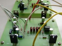
This project went from paper to prototype to PCB in the space of six months. I would like to thank everyone who posted here with suggestions and information, and also those who took a chance and bought the first batch of beta-boards.
The Phonoclone story continues at
Phonoclone Help Desk
-rjm
The Phonoclone story continues at
Phonoclone Help Desk
-rjm
Attachments
- Status
- Not open for further replies.
- Home
- Source & Line
- Analogue Source
- Phonoclone Update