noisy pc affect my sound card
how do you set up your sound cards
I got DMX 6fire sound card 24/96 and when measure Input / output I have s/n 60 dB
would you advise what to do to get better s/n
sound card use PCI
how do you set up your sound cards
I got DMX 6fire sound card 24/96 and when measure Input / output I have s/n 60 dB
would you advise what to do to get better s/n
sound card use PCI
OT, but ok: Check the specification of the card to see what you should have. A good idea to move the poer setting from "balanced" to "battery" to stop the CPU from changing from constantly adjusting the clock frequency which in my experience causing clicking noises through the audio output. Check the recording and playback levels in windows to make sure the gain is not set too high. Finally, check with Rightmark to measure your soundcard performance, it will give you a spectrum analysis of the noise so you will understand better where it comes from, as well as give you a full performance evaluation.
Totally unrelated, I am trying out Twitter. You can find me (I think) at @rjmaudio.
/rjm
Totally unrelated, I am trying out Twitter. You can find me (I think) at @rjmaudio.
/rjm
I have received some 768k resistors from JBdv. Thanks.
Can't remember who but anyone from Perth/Australia requiring a pair please pm me with address.
I have sorted out the hum problems. It's only on my second string system which I need to work on.
Haven't done much listening this week but it's powered up. So far it has made the DL103R sound better to me and the ATF9 a bit too bright. If that is the way it stays, what would tame the treble?
The input impedence of my Bryston BP-25 is 48k and the old Adcom GFP555 which I think is 20k but not sure.
Needless to say I didn't receive the bits Rhys missed out of the kit and said he would send. I'm just glad I got it at all, plus 4 spare 220k and an 8pin socket.
Kffern
@rjm tnx for bringing back the concept of the phonoclone back to me (gain is controlled by impedance of cartridge)
Question: with this PC3 concept: how important is (what is the influence of) the tonearm wiring plus interlink to the PC3?
JBdV
Question: with this PC3 concept: how important is (what is the influence of) the tonearm wiring plus interlink to the PC3?
JBdV
regarding the binding post:
yours looks nice Renato (but a bit far away ;-)
so I looked further and only found this:
http://nl.farnell.com/jsp/search/productdetail.jsp?sku=1101093&_requestid=695195
(no shipping charges)
Mine is a bit thicker, but of course from a functional point of view a plain bolt would do.
yours looks nice Renato (but a bit far away ;-)
so I looked further and only found this:
http://nl.farnell.com/jsp/search/productdetail.jsp?sku=1101093&_requestid=695195
(no shipping charges)
Mine is a bit thicker, but of course from a functional point of view a plain bolt would do.
@rjm
I know input in my preamp has cap, and also think about testing Phonoclone 3 and some OpAmps etc. without the C3 cap
Still I have the input impedance in the preamp on the 47K..
What about some change for R7 + R8, when I and others run the phonoclone without C3
I know input in my preamp has cap, and also think about testing Phonoclone 3 and some OpAmps etc. without the C3 cap
Still I have the input impedance in the preamp on the 47K..
What about some change for R7 + R8, when I and others run the phonoclone without C3
Hello everybody.
This is my first post, please excuse me for my english.
I've completed my PC3 and in this first post I would like to thanks Rjm for the project and all of you for all the informations shared here.
Until this morning everything worked well, and I was thinking to post here the photos and my first impressions about the sound.
But... this morning I've found the PSU very, very hot, with a smell of plastic. Immediately I've disconnected the power but too late: the two toroidal were burned ( the primaries,tested with the multimeter, are in short circuit )!
All the plastic fast-on inside were completly melted!
I really don't understand how this could be happened: I.ve checked all the connections many times:
IEC L -->switch ->primary +
IEC N --> primary -;
The secondaries go to the bridges, all the connections checked for + and -.
I listened for two days without any problem ( no hum, no noise, just a radio in the background , great sound!).
Maybe I've connected the IEC/switch/neon in a wrong way? I've done like this:
IEC+ --> switch out 1
Primary+ --> switch out 2
IEC- -->Primary -
Any idea, advice, explanation before I try with other toroids?
Thank you very much to all.
G.
No fuse on the AC line? That's poor technique.
Still, it's pretty hard to imagine hooking up the power transformer incorrectly and still having the phonoclone work properly so I'm willing to give you the benefit of the doubt and believe you when you say you checked everything.
Perhaps you should post photos anyway. I think it would be instructive. Seeing the area around the power transformer would tell me more about what could have gone wrong.
Possibilties:
- Transformer was damaged / faulty.
- Poor soldering or crossed wires shorted the power rail (V++ or V--) to ground.
- ???
Thanks, Rjm, for the answer.
Well, I'm just a beginner ( this is my third project after another pre-phono and an mc step-up), but the fuse was there: I've used a IEC/fuse/switch (with neon lamp ).
The fuse is still working ( but I've seen that it's a rapid 1A), so the switch.
The toroids were mounted in this way:
- skrew througth the base of the box ( alluminium hammond )
- a sheet of thermal insulation
- the first round metal cover of the transformer with his insulation
- at the top of the toroid the insulation then the second metal cover
- after the bolts, a second sheet of thermal insulation
No contact between the base and the top of the box.
I've soldered the rectifier bridges and the secondary, every contact was covered with a thermal-shrink.
I'll take some photos today.
I don't know if the phonoclone is damaged. How can I test this without connect a power source?
Thank you for the help
Giuseppe
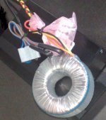
I've taken some photos of the psu and the PC3, trying to show also how the parts had been mounted inside the box, how the primaries connect to the switch and so on.
You'll find also a picture of the procuct I use to insualte.
I hope that someone could explain me what is wrong.
Thank you very much
Giuseppe
http://www.chromatron.it/ftp/fotoPC3.zip
You'll find also a picture of the procuct I use to insualte.
I hope that someone could explain me what is wrong.
Thank you very much
Giuseppe
http://www.chromatron.it/ftp/fotoPC3.zip
some suggestions:
working on assembling a power supply with mains voltage and fuses in the mains power line is responsible work and needs to be done very thoroughly
solder work/skills need to be improved, an altenative may be using screw connections for the power supply assembly
use 1 transformer and 1 rectifier bridge to simplify the assembly of the power supply (there are most likely only very few that could hear the difference in audio performance)
I don't want to be blunt, but safety is very important !!!!
GiusB said:The toroids were mounted in this way:
- skrew througth the base of the box ( alluminium hammond )
- a sheet of thermal insulation
- the first round metal cover of the transformer with his insulation
- at the top of the toroid the insulation then the second metal cover
- after the bolts, a second sheet of thermal insulation
No contact between the base and the top of the box.
Giuseppe [/B]
Giuseppe don't use all that isolation and two round metal cover..
1) remove the lower sheet of thermal isolation
(toroid need all of the box metal to remove heat)
2) remove the lower round metal cover
3) remove second sheet of thermal insolation (as 1)
... like this
- skrew througth the base of the box
- the first round insolation
- at the top of the toroid the insolation
- the second metal cover
- the bolts
4) 4xbridge also need a skrew for contact to alluminium in the box for cooling.
because of the very low power usage of the PC3 heat should be no issue inside the power supply housing
In my own PC3 power supply I cannot detect any part that is hotter then the room temperature
I run the PC3 24/7 (until I will be able to have it automaticaly switched by the end amplifier)
I just forget switching it off all the time
The heat issue that caused the malfunction must have a wring/connection issue as cause
I wonder if the ends of the bolts holding the transformers touched the lid of the case when closed? That seems the most likely explanation for what happened.
The photos show a power supply that is cramped but while its not the neatest soldering, it seems otherwise satisfactory.
Note: if going dual mono, either build two identical power supplies ... or use a bigger base than the 1590D.
The photos show a power supply that is cramped but while its not the neatest soldering, it seems otherwise satisfactory.
Note: if going dual mono, either build two identical power supplies ... or use a bigger base than the 1590D.
thank you very much for the answers.
@JBdV:
you're right, but I can assure that I've paid the maximum attention; also I started with screws, but there was not enough space inside the case. Anyway, this second round, i'll try with just one transformer.
I agree that must have a wring/connection issue, but where?
Thanks for the advices.
@FinnC:
Ok, I'll do this way. I used the insulation not only for thermal problems but to avoid contacts between the case and the toroids. My fault.
About the screw for the bridges, I really didn't know. Can you please show me how I can do this safety? Thanks.
@rjm:
No, I'm sure because I put a second sheet of insulation between the top and the transformers ( you can see it in the photos ).
You're right, not too space. May be the problem?? I've seen other PSU cramped more than this. Anyway I'll start putting just one transformer in the same case, to see. Thank you.
So, the mystery remain: it worked for two days, and it was cold ( I've touched the psu before go to sleep ). In the morning it was fused. I think that some contacts became instable because of the poor space, but I've re-checked anything and I can't see any fault.
On the other hand it's just no possible that I took two faulty transformers in one shot!
Thank you very much to everybody, I promise to not bother anymore with this story.
Giuseppe
hello GiusB, please feel to post whatever issues you run into.
There will always be people willing to response, and they may even help you finding the cause of the issue
I am trying to post my first picture on this forum. When I succeed you will see how I build the prototype of my power supply with very little effort just using a few screw blocks and 4 seperate diodes.
Right now I am working on finalizing the power supply.
Picture may follow later.
An externally hosted image should be here but it was not working when we last tested it.
Attachments
GiusB said:@FinnC:
Ok, I'll do this way. I used the insulation not only for thermal problems but to avoid contacts between the case and the toroids. My fault.
About the screw for the bridges, I really didn't know. Can you please show me how I can do this safety? Thanks.
Giuseppe [/B]
And no, normally you don't get two toroids with fault.. but this fault - I can't see it.
The lower round metal cover: The only I found (as rjm) was that toroids don't like steel/iron 'very close' and all around it - together with the bolt in the center this can works like another 'secondary'.
Normally the Phonoclone not draw lot of power, so if you don't connect the Phonoclone to the PSU, you can check if the PSU warm up without anything connected.
And now One hand in the pocket

Don't ever do this with mains on. Let the PSU run some time, then remove the mains - off and remove cable. With the other hand, you can feel if toroid get very warm or a bridge..
Temp. is after some time between room temperature and your own finger temp.
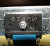
Attach: Image for bridge. Another type I use, but use it the same way as with toroid - the center and small bolt + nut for yours bridges.
Attachments
- Home
- Source & Line
- Analogue Source
- Phonoclone 3