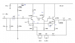
Here is a phono stage that i picked up from the past
Goal is to reproduce a more vintage sound with probably some of the problems that originate from that era
What i need :
A) someone to look at the circuit for a screaming mistake ( that actual thing is now made to a pcb and working surprisingly quiet ( hiss or noise ) gain is plenty and sounds extremely sweet
B) it bothers me that feedback is taken after the output capacitor if something goes wrong and the next stage is DC coupling you are doomed So i wonder if its safer to take it behind the capacitor and if this is expected to alter the sound or anything else ..
I used highest available quality parts , i designed a very quiet power supply behind it , and i matched all the transistors very carefully ...
Any thoughts on that will be very welcome ...
Thank you gents
Attachments

Last edited by a moderator:
Here is a phono stage that i picked up from the past
The polarity of the input and output capacitors is reversed, but I'd use NP types anyway.
The sound quality may be better if the RIAA is connected before the output cap,
but then the value and quality of that cap become more critical. It would have to be larger.
Last edited:
I used non polar capacitors any way ...MKS
and yes you are right this is just a drawing mistake
Kind regards
Sakis
and yes you are right this is just a drawing mistake
Kind regards
Sakis
I used non polar capacitors any way ...MKS.
What load will the stage see, can you still use a film cap if it's outside the nfb loop?
Well i cannot answer that I will need some help
It is working perfectly though as we speak ( haven't measured anything yet just listening to it and next to the phone stage that exists in pioneer SA8500II it has more gain , it has better ends and seems that the sound is very pleasant and in no case you need to use loudness at any level )
It is working perfectly though as we speak ( haven't measured anything yet just listening to it and next to the phone stage that exists in pioneer SA8500II it has more gain , it has better ends and seems that the sound is very pleasant and in no case you need to use loudness at any level )
Farther more in the original schematic the output capacitor was non polar electrolytic 0.15 uf i thought that this was very low and i went with 1uf MKT +0.1 byppas
Farther more in the original schematic the output capacitor was non polar electrolytic 0.15 uf
i thought that this was very low and i went with 1uf MKT +0.1 byppas
If the volume control is 10k, then the (open loop) pole would be at 14Hz, maybe too high.
Looks like the 120k resistor should be connected to the emitter of the BC550; this isn't clear on the schematic, as there is no dot where the wires cross....look at the circuit for a screaming mistake
Both ends of the feedback network are at ground (0 volts), so there shouldn't be any problem DC coupling to a subsequent stage. Other than the usual problems that always go with DC coupling, that is!...it bothers me that feedback is taken after the output capacitor if something goes wrong and the next stage is DC coupling you are doomed
-Gnobuddy
I wanted to say that i can easily double the output cap to 2.2uf Will that be ok ?
Yes, that should be good enough for using the output coupling capacitor after the RIAA feedback loop,
instead of inside it. You could try listening to the circuit both ways, since either way has 0VDC output.
Last edited:
Looks like the 120k resistor should be connected to the emitter of the BC550; this isn't clear on the schematic, as there is no dot where the wires cross.
Both ends of the feedback network are at ground (0 volts), so there shouldn't be any problem DC coupling to a subsequent stage. Other than the usual problems that always go with DC coupling, that is!
-Gnobuddy
OK got it dot was supposed to be there another drawing error ...( that doesn't bother me 😀)
Got the feedback issue
Any other comments ?
Looks like the 120k resistor should be connected to the emitter of the BC550;
this isn't clear on the schematic, as there is no dot where the wires cross.
Definitely, that is correct.
Well as said it has edgy type of sound either way Bass is deep and plenty one of the few phono stages that i listened to ( in reference with typical generic phono stages existing in consumer HIFI amplifiers ) that has such a rich sound ....
tested with ortofon red , OM 2 ortofon , Audio Technica AT 95...
From the schematic though is missing dip switches fro selecting 3 types of loading for various cartridges from 47-220 pf and from 47-220K and all avaible combinations
tested with ortofon red , OM 2 ortofon , Audio Technica AT 95...
From the schematic though is missing dip switches fro selecting 3 types of loading for various cartridges from 47-220 pf and from 47-220K and all avaible combinations
Little errors like this happen to all of us, of course. But I do hope you post a corrected schematic, in case someone else tries to build the same circuit, and can't figure out the mistakes in the schematic. It could really frustrate a newbie.OK got it dot was supposed to be there another drawing error ...( that doesn't bother me 😀)
There are a few other places in the schematic with missing dots as well, so right now it is hard to tell from the drawing which wires cross, and which ones join.
I know you can tell which is which, because you built the circuit, and it's working! 🙂 I too can tell which is which, because I understand how the circuit works, but what about newcomers to electronics?
Here are a few of those other missing dot locations on the schematic:
1) 160 ohm feedback resistor to ground.
2) Collector of leftmost BC 550.
3) Junction of 47 uF and 160 ohm.
4) 680k feedback resistor (both ends).
5) 12k feedback resistor (both ends).
6) Junction of 3k3, 3k3, and 120k resistors (emitter network of rightmost BC 550).
6) Junction of 150k with ground rail (BC 560 collector resistor).
7) Emitter of rightmost BC 550.
Hope that helps...
-Gnobuddy
If I look closely, there's a small grey dot at connections. Whereas crossing wires are all black. I agree that visibility is awful and schematic should be updated to reflect as built working circuit.
No one notice the first C backwards ?
Maybe you should re-read post #2
Oups you are right, I missed bothMaybe you should re-read post #2

Mona
I see tiny grey dots at some connections, but not at any of the connections I listed in my previous post. And all those listed points should be connections, not crossing wires. 🙂If I look closely, there's a small grey dot at connections.
I agree, even when the grey dots are present, they are too tiny to be noticed easily.visibility is awful and schematic should be updated to reflect as built working circuit.
-Gnobuddy
- Status
- Not open for further replies.
- Home
- Amplifiers
- Solid State
- Phono stage from the past ....