...What really matters to me is measuring of the circuit after implemented This is what counts simulation is good enough to calculate electric situations. Just an indication..The actual "product" will be way far from that .
Sakis
That is so untrue. Obviously you don't know how to use spice simulator properly.
Spice simulator can predict crosstalk from a bad input selector ?
Spice simulator can predict a very bad implemented PCB ?
Spice simulator can predict a bad and noisy implemented ground scheme ?
You cant be serious about that ....
Spice simulator can predict a very bad implemented PCB ?
Spice simulator can predict a bad and noisy implemented ground scheme ?
You cant be serious about that ....
Spice simulator can predict crosstalk from a bad input selector ?
Spice simulator can predict a very bad implemented PCB ?
Spice simulator can predict a bad and noisy implemented ground scheme ?
You cant be serious about that ....
OK, I just said what I have to say.
Layout and grounding(partially) is not spice task.
What bad input selector has to do with spice simulation.
A spice simulation is not finished job of course, you have to have other virtues too, but is not what you said.
Dadod ....
What i tried to say that a well simulated circuit or circuit that simulates well is only the basis ... After that, all details as described previously will have some impact in the audio quality and performance which you will only find out if construct and measure .
In the end goal is to listen to the product not the simulation ....
Kind regards
Sakis
Last edited:
Dadod ....
What i tried to say that a well simulated circuit or circuit that simulates well is only the basis ... After that, all details as described previously will have some impact in the audio quality and performance which you will only find out if construct and measure .
In the end goal is to listen to the product not the simulation ....
Kind regards
Sakis
Sakis,
I am not sure what you mean only the basis?
"This is what counts simulation is good enough to calculate electric situations", is that it?
If simulation done competently, the practical real circuit could be quite close to the simulation result, if someone does not destroy it with very bad layout or "improvements".
With some basic circuitry, like P3A, you can do without simulation, but with more complex, forget it(not so long ago with no simulators or to expensive, it was painful job).
best wishes, Damir
Damir it seems that we play some kind of word game ...But since English is not my native language i can try to explain it better if i manage .
I can place an example if you want ,where there is going to be a number of things that simulations cannot predict but in reality can and will effect the result ...here problem is that things like that are added to the final result .
Let me start with the most simple ...input capacitor is 1uf so we have
1uf electrolytic
1uf electrolytic 0.1uf bypassed
1uf bipolar
1uf bipolar 0.1uf bypassed
1uf MKT
1uf MKP
1uf MKS
1uf MKT 0.1uf bypassed
1uf MKP 0.1uf bypassed
1uf MKS 0.1uf bypassed
Now expect any of those to have small tiny variations in the sonic performance can you simulate that ?
Problem is that all of them are acceptable solutions and all of them will play Still there is going to be some difference in the sonic performance .
I will estimate this to a level between 2-3% ( for many other this is way much more )
Now choice of output capacitor will add for sure another 5-8%
Then choice of semis all your BC 550-560 in your simulator have hfe of 400 ( example ) all of them have exactly 400 hfe and all of them preserve their hfe at any given temperature
Can your simulator comment about that ?
I will guarantee you that matching the transistors closely in respect with the other ch will add easily another 8% of audible improvement .
Farther more a BC 550 from NXP states an hfe of 270 no minimum no maximum
Fairchild BC 550 states 110 till 800
Question: can your simulator or anybody else suggest that for this application the wise choice is 300hfe ( for example ) I expect not ...
You have a page full and we only talked about 3 parts
This is what i mean ....about the simulation ...we haven't even touched other even more critical issue like power supply for example ...we have only talked about a couple of things and narrow the improvement to maybe 20% ....
Last edited:
I disagree with most of what is proposed/hypothesised in post46.
Yes Andrew I agree.
I can't argue with Sakis as mine and Sakis opinion about components influents are to much apart, it is futile to priced.
Member
Joined 2009
Paid Member
I respect that Sakis has much experience in these matters and what he communicates above appears to me as making good sense - he says that the simulation is based on limited models and that real world components and their behaviour will deviate from these models and have some impact on the sound - even though a small impact they are detectable to him. How would you disagree with that ?
I do find simulations invaluable.
I do find simulations invaluable.
I am at the stage of choosing semis regarding quality and hfe, Mixmatching an measuring has started ...
Attachments
Last edited:
I disagree with most of what is proposed/hypothesised in post46.
Andrew we have been there so many times in the past ...Why in every thread i have to repeat the same things ?
At east electronics even though in a small country we repair 1500 audio devices per year ..( this year i think we will manage just a bit higher )
what we do all day is to change capacitors
So yes we have tried them all in all possible combination , in all possible equipment , in all possible application ...
What we also do is take feedback from the costumers ..We have done that in equipment repeated 40-50 times for each consumer amplifier existing ...We have the statistics now Andrew .....
A case just yesterday
Client owns a Plinius phono stage brought it in to change the cartridge load ( in the specific phono stage this is not user selectable ) Plinius has a standard of 220pf Client wanted 100 pf .
Said to him i am poping the hatch any way is there anything else you wanted me to look ? Client said yes of course
All looked fine inside except from 4 Philips capacitors two of them 10uf measuring 8.2uf and about 9R ESR and another two 22uf measuring 18uf and about 6 R ESR ....
Replaced with Nippon same uf but far lower ESR LXY series
Client call us to complain that the middle was never the same like it was before and wondered if this has anything to do with the cartridge load .
I said no but it may has something to do with the small electrolytics
Client brings it in to replace the load back to 220pf No result
Client brings it in to put back the old electrolytics and he was happier
Client brings it back once more to try 100pf load and noticed a tiny bit of high more ....while middle is fine
Result :
Why Plinius might have only these 4 capacitors inside made from philips while all the others was made by another factory ? I cannot answer that
Do capacitor make and quality play some role in our equipment ???? YES big time .
Finally there is a very good chance that Philips capacitors in a phono stage exist for a reason or exist because this was available at the time
There is also a good chance that the Plinius plays correctly with correct capacitors inside only the costumer is simply used to the result produced by these specific capacitors that measure that amount of ESR
Nobody can tell ....
Result is that it plays role a role that simulators cannot predict ...
I could actually spend 2-3 days that is required to find out and measure what exactly these 4 capacitors effect but i have no time for that I would rather spent this time on my own phono stage .
If you had this amount of repair experience Andrew we could have a more valid discussion about that . I am very happy to hear that you disagree with something i wrote but please could you please be kind enough to write down a few things to validate your opinion ?
Others are welcome also ...
Last edited:
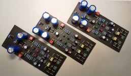
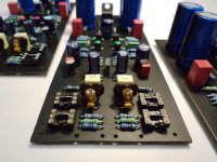
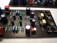
Hi Sakis,thanks for your very fine photos in posting #50. Well done!But what are these amber coloured components next to the input capacitors? Some of them are looking quite like LEDs?!?There's still one point left open: What's the correct value for the resistor between the supply line and the first voltage divider? Is it 100k, as shown in your schematics, or is it 180k, as discussed above?Best regards!
before input capacitors there is a block of capacitors and resistors to define the load of the cartridge since my drawing skills was discussed here i forgot to place this in the input of the phono stage .
In general only the schematic of the phono stage is in question here next to this will be the input block and of course the power supply ..
Amber parts are 100pf styroflex capacitors very rear for most people though sound and perform superb in filter applications .
Kind regards
Sakis
In general only the schematic of the phono stage is in question here next to this will be the input block and of course the power supply ..
Amber parts are 100pf styroflex capacitors very rear for most people though sound and perform superb in filter applications .
Kind regards
Sakis
As said at this point i am at the stage of measuring and analyzing the device so it is expected some things to change hopefully for the best
Stay tuned
Stay tuned
As said at this point i am at the stage of measuring and analyzing the device so it is expected some things to change hopefully for the best
Stay tuned
I swear I will 🙂!
Best regards!
In the very near feature i am designing a thread with things that simulators cannot predict all as described above with real measuring of what exactly this is doing anf how much in percentage may alter results for the best or for worst .
This to produce will take more than a week to make still i thing that there is something that i have to present
A procedure that is already done for the P3A for a period of many years considering my available time and since i am not willing to give away all my dirty secrets about the P3A i will present work done on the original schematic .
Stay tuned for that too in a new thread ...
- Status
- Not open for further replies.
- Home
- Amplifiers
- Solid State
- Phono stage from the past ....