A few things here - do you still get hum with shorting plugs on the input in place of your Turn Table (TT) input? If all is quiet then you definitely have a ground loop problem.
You should not feel anything touching the metalwork! the chassis work should be grounded and the source of the hum could be the chassis trying to find ground via the TT. Without seeing your set up it is difficult to advise but sometimes grounding the chassis of the amp and removing the ground from the TT (if fitted) may help. The partial live chassis however is not good and you should attempt to clear this first I think. Les
You should not feel anything touching the metalwork! the chassis work should be grounded and the source of the hum could be the chassis trying to find ground via the TT. Without seeing your set up it is difficult to advise but sometimes grounding the chassis of the amp and removing the ground from the TT (if fitted) may help. The partial live chassis however is not good and you should attempt to clear this first I think. Les
Unfortunately, I have "quadruple" checked everything including myself. 🙂 The phono stage has X300 gain so it overdrives my amp with the pot at max. setting. Nothing strange here. The chassis has eddy currents I can't get rid of, I know because my hand feels it. I don't know if this is the source of my problems but those currents are there the moment I plug in the AC cord OR any interconnect cable. Doesn't matter if the PT is on or off the chassis. Wired in or wired out. The chassis just needs a cable plugged in with some electricity in it to feel 'funny'. I have built many tube gear and this is the first time I'm really clueless about what's going on. I really don't want to bother anyone anymore with my problems, be glad it hasn't happened to you!
It's not a bother. Many of us have gone through the same things. But, if you have no noise with no input device, and noise when input is plugged in, that suggests a ground loop of some sort. Triple checking doesn't always help. I've often overlooked an obvious problem multiple times. A fresh set of eyes might spot something. Have you read this?: Audio Component Grounding and Interconnection - diyAudio
Sheldon
do you still get hum with shorting plugs on the input in place of your Turn Table (TT) input?
Yes, I do. It disappears when I short the outputs and also when I short the grid of the second stage.
The partial live chassis however is not good and you should attempt to clear this first I think.
I can't. I've been trying for two weeks now. I read only 100mV going up and down from chassis to house ground.
Have you read this?: Audio Component Grounding and Interconnection - diyAudio
Yes, I did.
I keep thinking it must be something in your PS. Is it a 100Hz hum you have? If you can, please post a photo.
I have changed the caps just in case. Nothing wrong with the caps, tomorrow I'll change the bridge rectifier. The diodes seem to be fine though; my DMM says so, the output voltage says so too. Photo? Not in the mood for pictures, I just feel like throwing it out of the window.
Since the noise floor is benign when no input is present, but it hums when you plug in something plus you are sure its the input tube, it could be it oscillates when introducing system wiring on input. One of the classic manifestations of oscillatory behavior beyond heat and microphony is harmonic noise. Does it have enough and direct to grid pin short legged grid stopper value?
plus you are sure its the input tube,
I am not sure of anything other that it hums when I plug in the RCAs from another equipment. Shorting the inputs when the cables are connected does NOT stop the hum. Shorting subsequent stages kills the hum, the little RF hash noise, everything: total silence. Remove the inputs without shorting anything and there's only a little hash noise, no hum. But the time for this fix is up. Tomorrow will be the last day, I'm not wasting my time anymore on this. Much easier to do it all over again in a different chassis, different layout, maybe even different schematic.
Does it have enough and direct to grid pin short legged grid stopper value?
Yeah.
If it turns too microphonic when you will knock on the input valve a bit when it hums, its very fishy it oscillates. If its only hum due to a loop or a field, it should stay as microphonic to a similar a knock as when not humming.
It's fixed! And it was never broken!! All this time the preamp has been in the 'lab', belly up and surrounded by other electrical equipment. This has never been a problem before but now it has. I installed the bottom cover, moved it to another room, used an AC plug which didn't have anything else connected to it and that was it. Hum's gone!!! It was picking hum either from the shared AC plug or from nearby equipment. It wasn't the TT because I had the same problem when any other gear was plugged in. I know I look silly now but there's always a first time! I hope someone learns something from this. Thanks for the help.
Cassiel, don't feel too bad.. I discovered not so long ago that the compact fluorescent lamps that light my bench also generate tons of EMI - I spent a lot of time diagnosing my computer based measurement set up only to discover that shutting of the lamps mostly cured the problem - additional shielding helped, but now I just turn those lights off. (There are other noise sources that aren't so easily dealt with like wifi, and wireless phones) Can't tell you how many hours I wasted figuring this out, and I knew those lamps were noisy - just didn't realize how effective they were at generating both conducted and radiated EMI.. 😀
It's fixed! And it was never broken!! All this time the preamp has been in the 'lab', belly up and surrounded by other electrical equipment. This has never been a problem before but now it has. I installed the bottom cover, moved it to another room, used an AC plug which didn't have anything else connected to it and that was it. Hum's gone!!! It was picking hum either from the shared AC plug or from nearby equipment. It wasn't the TT because I had the same problem when any other gear was plugged in. I know I look silly now but there's always a first time! I hope someone learns something from this. Thanks for the help.
Ah.... Yes. So happy that this thread somehow managed to help you.
So how does it sound for you? What sort of caps are you using in the riaa? Also, how are you regulating the volume?
It sounds good and it has a lot of gain. My amp's pot doesn't past the 3 point mark. There's no hum and hiss at this point but there's a little hum and hiss when it goes to 6 - don't want to know what happens when it gets to 10.
My RIAA caps are Silver Mica.
With my right hand. But I have some amps that do not have a potentiometer at the input. It is a bit of a problem because this phono can't go to a line stage as it is. A pot at the output is still a possibility although I don't like the idea very much. Something like this:
PhonoI
What do you think of it? What would be the output impedance with a 100k pot? I have a blue Alps somewhere waiting to be used.
My RIAA caps are Silver Mica.
Also, how are you regulating the volume?
With my right hand. But I have some amps that do not have a potentiometer at the input. It is a bit of a problem because this phono can't go to a line stage as it is. A pot at the output is still a possibility although I don't like the idea very much. Something like this:
PhonoI
What do you think of it? What would be the output impedance with a 100k pot? I have a blue Alps somewhere waiting to be used.
Just wanted to add that this is a good phono stage and that I have too much gain because my cartridge puts out 6.5mV. It isn't really a big problem anyway. If someone is interested in building a clone I'd say: go ahead, it's cheap and good sounding. You can change the CF tube for a 12au7, if you don't like the 12ax7 in this position, just by changing the cathode resistors from 120k to 68k. Cheers.
ok, so this is what I have been testing and it works very much nicer than regulating the volume with a pot on the output.
I bought a dual 2M log scale allen bradley potentiometer on ebay for $14. I use it to regulate input to the grid of the second valve. 😉
Honestly, the air caps in the riaa do sound best - but they take up a lot of space. AMCH are still very, very good and sound better than all of the silver micas I have tested (and I have tried quite a few).
I now put two smooth plate telefunken 12ax7's and a mullard cv4003 in the third position (with previously mentioned adaptation to cathode resistor).
The sound is VERY good. Not too much gain at all with my set-up. But it MUST have a good PS. This means valve rectification, chokes, motor run caps (not too much uF!)... and chokes on the heaters makes a big difference too. I have tried all sort sorts of power supplies, and nothing can replace a good choke!
Personally, I don't mind a little RF hash, since I find it so hard to find a resitor that sounds like a straight wire... coupling capacitors are also little deamons - I use Jensens but have some monster-sized russian PTFE's I may try to fit in the box. PTFE caps have almost no coupling capacitor signature to my ears.
Last edited:
A pot at the output is still a possibility although I don't like the idea very much. Something like this:
PhonoI
What do you think of it? What would be the output impedance with a 100k pot? I have a blue Alps somewhere waiting to be used.
If you have 100k on the output then that's your output impedance. its really kind of simple after the output coupling cap...
That circuit you posted uses a lot of TL's original mods for Ear 834p. That one has an output impedance of 28.8K (68K paralleled with 50K). No idea why he by-passes the output coupling cap. That looks like hokus-pokus to me, but maybe I am missing something.
I prefer the sound without cathode by-pass. I had already tried it with battery bias on the second stage instead - which works really well but you have to take it out when its not on, and put it in again when you want to use it. That's a bit of a pain, and the method in the romy cat circuit sounds just as good.
You could take your 100k alps blue, and bypass it with different restor values until you find levels to your liking. Then get a matched pair of quality matched Japan carbon films. I would start to bypass with a 100K resistor, then go down from there.
And you are right - regulating volume on the output will NOT be anywhere as satisfactory as regulating the grid. Try and find a nice old dual AB pot like I noted in my previous post. 😉
Last edited:
I bought a dual 2M log scale allen bradley potentiometer on ebay for $14. I use it to regulate input to the grid of the second valve.
Hey,hey! I like that idea. Then I can install a switch to bypass the feedback loop and use it as a guitar preamp as well. 😀 Seriously, I should have thought about that. It makes sense to me too. Best solution. Thanks for the idea.
About the PS- yes I like tube rectifiers, chokes and poly caps but my chassis is too elegant, too slim and too chic for all that weight. This is my first phono stage just to get my feet wet with this topology, I plan to build a monster PS some day because I'm sure I'd like it much, much better.
AMCH caps
Didn't know about them. I will check them out.
Can't find 2M dual log pots, it will have to be 1M. Why there's a 2M resistor there anyways? A better load for the first stage or it has something to do with something else? Anyone?
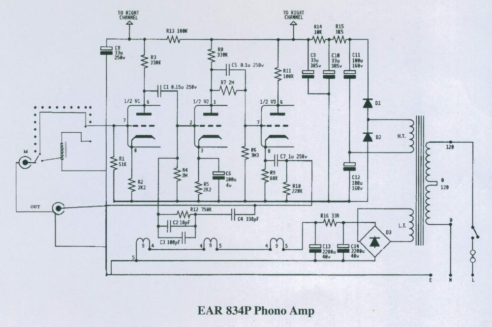
Can't find 2M dual log pots, it will have to be 1M. Why there's a 2M resistor there anyways? A better load for the first stage or it has something to do with something else? Anyone?
It forms a voltage divider with the grid resistor of the next stage (cathode follower), and sets the DC voltage for its grid. The capacitor in parallel, couples the AC voltage from the plate of the second stage to the follower grid.
Sheldon
Sorry, I didn't realize there were two 2M resistors in that schematic. I was talking about the grid leak resistor of the 2nd stage. I'm going to install a pot there and was wondering if it's OK a value of 1M.
Sorry, I didn't realize there were two 2M resistors in that schematic. I was talking about the grid leak resistor of the 2nd stage. I'm going to install a pot there and was wondering if it's OK a value of 1M.
Yes and no. Yes you can install a 1M pot there, but you will have to recalculate the RIAA compensation values, or your RIAA compensation curve will not be accurate.
If it's not going to be your main volume control, and you only need to attenuate up to half, then you can use the 1M pot in series with a 1M resistor.
Or, if you are not using the phono amp for volume control, but only want to adjust the gain to match your system, then you can use fixed resistors to divide down the output. The value of the divider string should be 2M if you want to keep the rest of the RIAA network as is.
Sheldon
Sheldon
- Status
- Not open for further replies.
- Home
- Amplifiers
- Tubes / Valves
- Phono Amplifier