I don't need to post a sim, I have an amp (not a UcD topology) running around 250kHz that will produce the full audio range.
Look near the end of this thread to see the design of the amp: http://www.diyaudio.com/forums/showthread.php?s=&threadid=87534&perpage=10&pagenumber=1
It's based on a TI TPA2001D1 modulator and TAS5261 output stage.
It's based on a TI TPA2001D1 modulator and TAS5261 output stage.
Hi, Fumac,
From your explenation, you don't use UCD topology for all your amps. In your UCD based topology, what is the voltage (p-p) of the residual output at idle?
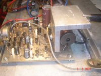
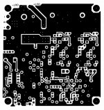
From the "high speed mode" PCB, you explain short tracks.
Do you got other explenation/examples for drawing high speed pcb?
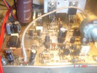
I see the picture of your board. You place the components on top side (while Hypex and Philips place it on bottom side, the top side is ground plane).
Do you use single or double side pcb? Do you use ground plane?
From your explenation, you don't use UCD topology for all your amps. In your UCD based topology, what is the voltage (p-p) of the residual output at idle?
From the "high speed mode" PCB, you explain short tracks.
Do you got other explenation/examples for drawing high speed pcb?
I see the picture of your board. You place the components on top side (while Hypex and Philips place it on bottom side, the top side is ground plane).
Do you use single or double side pcb? Do you use ground plane?
i used double side pcblumanauw said:Hi, Fumac,
From your explenation, you don't use UCD topology for all your amps. In your UCD based topology, what is the voltage (p-p) of the residual output at idle?
From the "high speed mode" PCB, you explain short tracks.
Do you got other explenation/examples for drawing high speed pcb?
I see the picture of your board. You place the components on top side (while Hypex and Philips place it on bottom side, the top side is ground plane).
Do you use single or double side pcb? Do you use ground plane?
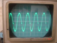
the voltage (p-p) of the residual output at idle
u can look this pic , about 0.175v
http://www.diyaudio.com/forums/showthread.php?s=&threadid=93787&perpage=10&pagenumber=2
it's base on the need, the test boar of philips is a right choice
i place the components on both side, because of the mini size i like.🙂
i place the components on both side, because of the mini size i like.🙂


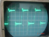
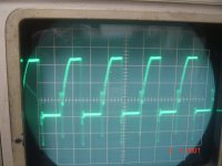
ringing is not only base on the pcb
but also must to Correction ur Probe
i use the high-speed Probe (tek 300MHz Probe)
the pwm is a very high speed ,dont use the low speed Probe to test it🙂
but also must to Correction ur Probe
i use the high-speed Probe (tek 300MHz Probe)
the pwm is a very high speed ,dont use the low speed Probe to test it🙂
U have got the way
Congratulations ¡I
No, no congratulations. I'm in headache here. 😀
Do you mean I have to redraw new PCB, with all SMD components?
SMD components are very difficult to solder.
Is it possible to use ordinary components, but still getting good result? No need 1mhz like you get, but getting 150mV residual is good enough.
Fumac, you got 150mV residual. How come the real UCD have only 20mV?
lumanauw said:
No, no congratulations. I'm in headache here. 😀
Do you mean I have to redraw new PCB, with all SMD components?
SMD components are very difficult to solder.
Is it possible to use ordinary components, but still getting good result? No need 1mhz like you get, but getting 150mV residual is good enough.
Fumac, you got 150mV residual. How come the real UCD have only 20mV?
150mv is P2P, i dont know the ucd 20mv is rms or p2p
i will have a new test after my new PCB🙂
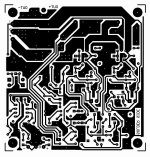
if u like ,u can post the PCB pictures here, let me have a look🙂
if u like ,u can post the PCB pictures here, let me have a look
OK, here's bottom layer
Attachments
- Status
- Not open for further replies.
- Home
- Amplifiers
- Class D
- Philips UCD application note