Awesome, I might get in touch about that later in the month, but even at a great price, 500 is a lot 😉
Re: Whilst we're on the subject of clocks
EDIT See above...damn I'm such a slow typist........
Andy
SimontY said:[B
Also, can we re-clock the DAC directly, separately from the digital filter, or must they be synchronised? The datasheet calls for a max of 6.4MHz, but in reality I don't know what frequency is needed at the bit clock input / pin 2.
..if they must be tied together, can the clock signal from the dig filter (SAA7220) be buffered on its way to the TDA1541A? Will this do good things?
[/B]
EDIT See above...damn I'm such a slow typist........
Andy
jean-paul said:The OSCONS are excellent for decoupling SAA7220. 100/20 is the right size and value but 220 uF 10 V is slightly better at that spot. But replace the series resistor for a coil too if you are going to change the supply of the SAA anyway.
I'm not interested in even trying non-OS. I have a dedicated low noise reg on each SAA, so there's no resistor to change. On the 7220 there's also an inductor in place on the board as standard.. I have ZA 220uF there at the moment iirc. I also have some 68uF/20V oscons (got for a cheap price) that I could double up for super-low ESR... what say ye?
Re: Re: Whilst we're on the subject of clocks
lol, so you agree I should try that?
poynton said:
EDIT See above...damn I'm such a slow typist........
lol, so you agree I should try that?
Simon,
Before you start worrying about the clock, get a 7220B in place. Its a big upgrade over the 7220A.
The reason that that clock division offboard works for many is that the 7220 handles digital filtering, clock division, drives the SPDIF output etc all in one large package that has the one power and ground pins on diagonally-oppoiste corners... ie is difficult to decouple well, and therefore prone to internal interference.
That's why a good reg here makes an enormous difference.
But if you can separate some of these tasks, you can get further gains:
http://www.diyaudio.com/forums/showthread.php?s=&threadid=99652
As I said, using one clock with a divider to feed the 7220 and the dac separately can work very well indeed, but you need to watch the delay between these two clock streams; IIRC some have found it necessary to add another inverter to one stream or the other to correct for delay across the 7220 digital filter. Do a search here in the Digital board for 'SAA7220' in the title will find 19 good threads to read...
Ahha, I've read some of that thread before. I'll do another pass of it. I'm going on a sort of working holiday (but not too much work) next week so I'll have lots of time to read threads lol
I'll read up on the other SAA7220 threads, and also get finding a source for a B revision of the chip. Have you heard of anyone selling these? I could post a WTB thread and see if someone has one I suppose...
Whilst on the subject of minimising roles of the '7220 Is it worth killing the digital output too?
Thanks!
Simon
Ah Simon,
Could you direct me towards the details of Lee's o/p stage? Missed that one.
You have a bit of a contradiction with those big Mundorf + Ruby ZA's.
Would suggest to go for smaller caps in a C-R-C setup plus a darlington Cmx to feed that S reg (and a secondary shunt reg to really go overboard!)
Then, perhaps, decouple with a Silmic (depending on the sound of that new O/P stage, naturally)
While you're at it, perhaps add a "Hagerman" R-C snubber across the output of those diodes (byv27, sf14s, etc) for clearer top end transients.
Now about reclocking and things - you'll need to have a look at the spec sheet of the 41A to keep this clear - search for the old thread "TDA1541 information" (diyAudio) and the "Ultimate 1541A Nos dac" thread.
Basically, you divide the master clock down to 5.6Meg to run the dac chip clock input directly (assuming the 7220 is set for 4 times o/sampling) and the other 2 inputs (Data and Word) from the 7220 are also reclocked before going to the Dac - i think I've got this right, as I delete the 7220 chip (NOS) and the dac chip now runs on 2.8 Mhz.
Next, you use the 1/32 division (352 kHz pin) to overdrive the DEM oscillator (pins 16, 17) via another buffer and inverter chip.
Surprisingly enough, it's not as bad as I've written it, but still not simple.
The clock needs "CLEAN" supplies, and the buffers also require seperate supplies too.
Gets a bit messy as the clock ties into Analogue earth but the reclock/buffer chips tie into digital earth.
I'm in the middle of ploughing thru all the technical stuff and looking to do a proto set of boards - some others have used a simplified version and apparently this totally transforms the dac's performance but demands an integrated approach to the power supplies.
This is all directly based on the current EC Design developments (Ultimate 1541A dac" thread, last few pages.)
There is an intriguing development called the Charge Transfer supply that i think will become an industry (or DIY) standard anyway. It's the perfect answer to noisy mains, diode Irr, etc and troublesome supply situations.
Trust Martin to quote the comedy thread! 
That is my best performance yet. Absolute laziness causing me to be in denial about the fact that yes, the clock to the 7220 and thus the I2S BCLK going to the DAC MUST be derived from the same clock. Otherwise, well, it ain't pretty 🙂 What a muppet I be.
Martin's right I did do a bit of buffering the I2S between the two chips. I basically used a set of flip flops ( 1 of 74xx174 if I recall) clocked by the 11MHz master clock. Really easy to implement, and surprisingly just worked. I didn't get round to just dividing the clock by 2 to provide the BCLK, but it should be as straightforward. Just a single flip flop (74xx74'll probably do).
I abandoned this when I started using the PMD100. Mainly because it was less necessary, but also because at 8x OS, the buffer may not be so useful (I can't remember if BCLK becomes 11MHz, or 5.66MHz, if 11, clocking that is really getting prone to issues {what happens when you clock at the exact time the edge changes, less likely at lower frequencies }). Ideally, for buffering, you'd need a higher clock frequency, but then it gets harder to implement.
However, again there may be merit in my reinvestigating this
jameshillj said:
There is an intriguing development called the Charge Transfer supply that i think will become an industry (or DIY) standard anyway. It's the perfect answer to noisy mains, diode Irr, etc and troublesome supply situations.
At a quick look, this seems like the "never-connected" power supply.
Andy
PHil - IIRC the bit clock stays at 5.66Mhz because it's the data format loaded to the 1541 which changes to allow 8x OS since it can only accept bitclocks up to about 6.4Mhz anyway.
Either way I'm really looking forward to hearing your PMD100 implementation next week!
Either way I'm really looking forward to hearing your PMD100 implementation next week!
Yeah Andy, it does, doesn't it - a Fenson's (UK) project.
There has been some discussion about whether it's an original development or owes it's genesis to earlier work. I see they're claiming a patent, but no number tho. a maybe.
Not a cheap little upgrade for a cd player, preamp, etc by any means. I think Max Lorenz has adapted it for higher current to run his classD amp with excellent results - he said it was rather simple using John's (EC Design) early cct with just the + and - lines seperated - the latest design uses the transistor/fet switching on both the power rails and the 0volt to give complete isolation.
I don't think this is done by Fentons, but could easily be wrong.
Either way, it's a remarkable development that will make a significant impact on our gear.
jameshillj said:.............
There has been some discussion about whether it's an original development or owes it's genesis to earlier work. I see they're claiming a patent, but no number tho. a maybe.
............. - the latest design uses the transistor/fet switching on both the power rails and the 0volt to give complete isolation.
...........................
Either way, it's a remarkable development that will make a significant impact on our gear.
I repaired a commercial psu once that was used to power a clock, build quality was nothing special!!!
It states that it isolates the circuitry from mains borne noise but as we have seen, in cd players, most of the noise is internally generated by the digital section
So, IMO, it may be an expensive way to solve a (no-existant) problem.
Andy
Re: Re: S2 Double Crown
Agreed! All the mods obviously add up but I'd definately say the quick wins are seperating the 5v supply's to these chips. Even std 7805's independantly supplying these 2 is a very big win.
SPowers take it up another level 😀
Ian
SimontY said:
It wasn't for me, probably because some other areas were so lacking. The most exciting mods were S Power regulation on the 7220, Super Reg on the 7210 and new caps on the mech board. These mods cleaned the sound right up. Mind you, super reg on the DAC +5V was awesome too...
Agreed! All the mods obviously add up but I'd definately say the quick wins are seperating the 5v supply's to these chips. Even std 7805's independantly supplying these 2 is a very big win.
SPowers take it up another level 😀
Ian
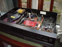
hello fellas - I've been lurking about for a day or so now while I awaited delivery of another super cheap ebay bargain - a Mission PCM4000 for a whole £11 🙂 - it is of course effectively a Philips CD650 in disguise - hence my interest in this fab thread!
Well it arrived this morning - and tbh I didn't really expect it work since it was packed in a box 3 times too big with no more than a single sheet of bubble wrap around it!😱 😱 - anyway work it did - and OMG - it sounded pretty damn fine too - all warm and cosy - top end wasn't exactly sparkling but nice all the same. Hmmmm - this is interesting.
back in the good ole 80's I went through a bucketload of Philips players but don't remember sounds like this!!
anyway - exactly 45mins & 1 album later, the top came off for a peek inside - you'll no doubt recognise the innards!
First things first - out with those 5532's and in with a couple of decent 8pin Sockets for a spot of opamp rollin - straight back downstairs with a brace of LM4562s fitted. Same album again - oh yes - a spot of clarity at the top end now - i am liking this a lot.
lunch and another couple of albums later I'm thinking it's time to address some power supply issues. On goes the iron again and a trio of OSCONs go in by the DAC in place of those little Nichicon 47u's. At this point of course it would have been sensible to stop and go have another listen .............................. but you know how it is - 😉 - the board is out and just begging for some more action . So on goes the iron again and the 5v supply for the 7220 is seperated from the other dozen things that use it and a basic 7805 is strapped in there to feed the 7220 alone.
back downstairs - and on goes album no 1 again - OMG ...... OMFG!! - it must be that reg. on the 7220 - it's nowt special of course - but hell what a difference - dramatic - and I use that word deliberately! - real solidity to the music - and yet much improved space around instruments. ........ OH YEAH!! - this is gonna be fun alright.. 😀
I am just about resisting the temptation to just go balls out and do more in one go - psu diodes, non-os mod - rest of the lytics etc. - for now I'm gonna get used to this - at least 'til the weekend! 😀
anyway - ta for the great info on the thread guys - haven't managed to get hold of a schematic yet - are there any working links about still? - all the ones I tried are dead.
I shall read on with great interest - cheers again fellas.
Well it arrived this morning - and tbh I didn't really expect it work since it was packed in a box 3 times too big with no more than a single sheet of bubble wrap around it!😱 😱 - anyway work it did - and OMG - it sounded pretty damn fine too - all warm and cosy - top end wasn't exactly sparkling but nice all the same. Hmmmm - this is interesting.
back in the good ole 80's I went through a bucketload of Philips players but don't remember sounds like this!!
anyway - exactly 45mins & 1 album later, the top came off for a peek inside - you'll no doubt recognise the innards!
First things first - out with those 5532's and in with a couple of decent 8pin Sockets for a spot of opamp rollin - straight back downstairs with a brace of LM4562s fitted. Same album again - oh yes - a spot of clarity at the top end now - i am liking this a lot.
lunch and another couple of albums later I'm thinking it's time to address some power supply issues. On goes the iron again and a trio of OSCONs go in by the DAC in place of those little Nichicon 47u's. At this point of course it would have been sensible to stop and go have another listen .............................. but you know how it is - 😉 - the board is out and just begging for some more action . So on goes the iron again and the 5v supply for the 7220 is seperated from the other dozen things that use it and a basic 7805 is strapped in there to feed the 7220 alone.
back downstairs - and on goes album no 1 again - OMG ...... OMFG!!
- it must be that reg. on the 7220 - it's nowt special of course - but hell what a difference - dramatic - and I use that word deliberately! - real solidity to the music - and yet much improved space around instruments. ........ OH YEAH!! - this is gonna be fun alright.. 😀 I am just about resisting the temptation to just go balls out and do more in one go - psu diodes, non-os mod - rest of the lytics etc. - for now I'm gonna get used to this - at least 'til the weekend! 😀
anyway - ta for the great info on the thread guys - haven't managed to get hold of a schematic yet - are there any working links about still? - all the ones I tried are dead.
I shall read on with great interest - cheers again fellas.
Attachments
LMAO - that looks familiar, well it would've done about 4 months ago 
I couldn't find a service manual for the CD650, but I do have one for the CD640 and CD660, as well as TDA1541A, TDA5708, TDA5709, SAA7210, SAA7220, L272 - all easy enough to find, and free.
I can e-mail you these if you like, save you hunting them down.
I'm not surprised by your reaction to isolating the SAA7220. The same level of wow (more or less) will happen when you do the SAA7210 (big chip with small RAM IC next to it). I think you would be shocked to hear mine now. It's unbelievably removed from the standard sound.
Simon
Yes, isolating that 7220 is very important thing to do.
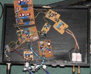
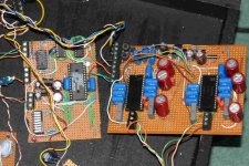
I'll see if I can get some pictures of my DAC up - I can assure you it won't look familiar 🙂 - Might also prepare Martin for the shock of what he has to plug into his system next week😉 - although he's seen it before.
LMAO - that looks familiar, well it would've done about 4 months ago
I'll see if I can get some pictures of my DAC up - I can assure you it won't look familiar 🙂 - Might also prepare Martin for the shock of what he has to plug into his system next week😉 - although he's seen it before.
- Home
- Source & Line
- Digital Source
- Philips CD650 mods