rfbrw said:You need inverted copies of DLCF and DRCF. To the left channel dac goes DLCF+ and DLCF- and the same for DRCF. A 74HC86 will do.
Thank you RFBRW for your advice.
The datasheet of the 74HC86 shows a propagation delay
between input and output.
My question is now with respect to timing is it not necesary to give CLCF and STR1 (from the SAA7000) also a delay (with a shift register IC f.i. or simple also a 74HC86 ) ??
Onno
For CD104 modders with crappy email accounts :
Let me know your email address and I will send you a link with username and password so you can download the service manual.
I still have an unfinished CD104 so the more input on this thread the better.😀
Jeroen
Let me know your email address and I will send you a link with username and password so you can download the service manual.
I still have an unfinished CD104 so the more input on this thread the better.😀
Jeroen
CD104 mod with 2 TDA1541a's
Still 2 tda1541a's parallel (only data, clock lines and outputs)
Connected 180 pf between pins 16 for better clock sync)
In the I/V replaced the two 22 mf (output DC decoupler) with 1 mf
(used the 4 470nf from the old tda1540p conf- 2 parallel).
(my preamp has high Z in !)
bridged the 1.8 k (between pin 1 and 2 opamp) with 2.2 k to get
abouit 4ma current in both dacs.
O.C you can replace the 1k8 by 1k)
Result is IHMO !!! better specially when the dac' s have a lot to do (f.i. in full orkestral passages)
Tried to put "low pass"30 ohm in serie with the 4 data-clock lines from the SAA7000 to the TDA1541a's but IHMO the soundstage was less "stereo".
Onno
Nuvistors??
Really impressed that the old 104 has such a following! I have one currently gathering dust in its plastic-bag in a cupboard......
After reading most of this thread it inspires me to dig it out.......
Anyone tried Nuvistors in the CD104?
The 7586 is a medium Mu Nuvistor type with a low supply requirements 40V is mentioned in the RCA data sheet for class A operation....
A low voltage type like this will save all that doubler/tripler/hum problem. I use them in the front end of my OTL. Sound very clean, but some Nuvistors can be michrophonic, but less so at lower voltages Ive found....
Onnosr said:
Thank you RFBRW for your advice.
The datasheet of the 74HC86 shows a propagation delay
between input and output.
My question is now with respect to timing is it not necesary to give CLCF and STR1 (from the SAA7000) also a delay (with a shift register IC f.i. or simple also a 74HC86 ) ??
Onno
On second thoughts, it isnt necessary to do anything with the other lines.
rfbrw said:
On second thoughts, it isnt necessary to do anything with the other lines.
rfbfw thanks for second thoughts.
I gonna give it a try (I have already a 74hc86
Regards
Onno
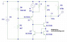
Because i got a lot of emails about the 4 transistor I/V solution i used in my cd104 i have made a screen dump of my Orcad design.
Note that it runs on -15 Volt and the output is the Voltage probe. The AC current source is the DAC of course. And the original design is by www.ultranalog.com
Let me know the results if you build it 🙂
Note that it runs on -15 Volt and the output is the Voltage probe. The AC current source is the DAC of course. And the original design is by www.ultranalog.com
Let me know the results if you build it 🙂
Attachments
Hi Guys.
Three days ago, my ancient Philips CD100 stopped reading the TOC.
It happened when I changed from one CD to another. Just like that.
I've been monitoring this forum the past months in order to gather information regarding reparing and upgrading this delicate piece of technology.
This site has also been an excellent source, since I'm planning the constuction of DIY Electrostatic Speakers.
Anyway.
I've come so far, that I need to resolder and replace a couple of caps and I trust my skills enough to be able to do the job properly.
But I'm in a really desperate need of a ServiceManual for the CD100.
If one of you have it, I'll be grateful if you'd mail it to me at DK6400Brian(a)gmail.com
I also have a CD104, that has the thermic symptoms and a CD207 that works perfect.
Those ServiceManuals are also very welcomed.
I thank you in advance.
Regards - Brian Baldersbaek
I thank you 🙂
I'm still in need of the CD100 and CD207 manuals though.
CD100, first priority of course.
I pulled the CD100 off the 230Volts and plugged it in, in my livingroom two hours ago.
To my surprise, it now works 😕
It must be unstable, so I'll go through the resoldering procedure.
Filling in new caps, also seems to extend the lifespand of this excellent machinery.
Even though this is a 23-24 year old piece of equipment, it fills me with joy and true pleasure every single time I power it up.
If it's possible to love a machine, then I love this CD100 😀
The tweaks and upgrading procedures within this forum is so much treasured.
I hope that I can contribute with knowledge, some time in the future.
For the time being, I hope it's allright that I stick my nosy nose in front, waving the desperate flags once in a while 🙂
MidiMaze said:Because i got a lot of emails about the 4 transistor I/V solution i used in my cd104 i have made a screen dump of my Orcad design.
Note that it runs on -15 Volt and the output is the Voltage probe. The AC current source is the DAC of course. And the original design is by www.ultranalog.com
Let me know the results if you build it 🙂
Hi MidiMaze,
Looks nice and simple (discrete components !!)
Do you use it with the tda1540p in NOS ?
Do you use it without any (lowpass) filtering ?
Do you know how much (mili)amps it takes from the 15 volts ?
Thanks for answering.
Best regards
Onno
CD104 Tweaks
CD104 - NOS - with two TDA1541A
I tweaked now two CD104's ( I have 5 of them)
One with expensive decoupler condensators. (0.1 MF)
One with cheap ones from an old 386 mamma pc board
I still have to find out wich one sounds the best.
I tried to put the TDA's in balance with no succes.
Now in place of the old left channel TDA1540 is sitting a TDA 1541a with left and right channel data inputs and analog right and left channel outputs parallelled.
OC the same for right channel.
(the two other lines (LE, BCK)are paralled to both TDA's and pin
27 is low -5 v (simultaneous op)
In the I/V stages the 1.8 k resistors are parallelled with 2k2.
Changed the 22 mf output decouplers to 10 mf tantaliums.
On the power unit a 7905 is added. On heathsink)
The 9718 is replaced by a 7915.
All regulaters ( 7924 and 7915) are moved to the heathsink.
(OC the SAA 7030 is removed -NOS)
On the SAA7000 pin 16 has to stay low (16 bit)
IMHO result is nicer rounder more dynamic more vinyl etc sound compare to non tweaked non nos an tweaked nos + tda 1540p's.
This modification is easy to to.
FI no new PBC is needed etc.
Now I gonna rebuild the next CD104 and try out different I/V stages FI the one MidMaze posted and the nuvistor suggestion from Alastair E.
Attached some foto's in this and next post.
PS 1
Connection jumper wires on the SAA7030 place are NOT the
the same as original NOS + 1540p tweak.
Pin connections from SAA7000 to TDA1541a's
SAA 7000 TDA1541a left ch TDA 1541a Right ch
13 (data L) --> 3+4 (Data L R) (TDA L)
15 (dataR) --> 3+4 (Data L R) (TDA R)
14 (CLF) --> 2 (BCK) 2 (BCK)
12 (STR1) --> 1 (LE) 1 (LE)
----------------- 6+25 ----> I/V L
----------------- 6+25 ----> I/V R
16 (low= Grd) ....pin 27 conected to pin 25 -5 volt
PS 2 I believe a extern clock does not give any plus
The original clock signal from the Saa7000 goes direct to
the TDA's and the built in clock on the SAA 7000 is perfect !!
I connected the house of the xtal with a wire to the ground
(Do it quick on the xtal otherwise it is exit)
I put the Servo PBC in a slanting position with to standoff's to get it about 2 cm more away from the decoder board on the site where the TDA decoupler condensators are sitting.
Onno
Attachments
Onnosr said:
Do you use it with the tda1540p in NOS ?
Do you use it without any (lowpass) filtering ?
Do you know how much (mili)amps it takes from the 15 volts ?
I am using it in OS mode, i have had to much mathematics to understand why i shouldn't use NOS.... (i don't want any OS / NOS discussion here)
The filtering is done with the 100u cap and 470k resistor, this will give a nice first order fall-off.
I have no idea how much current it will drain from the -15 volt, but in my player it runs fine without running hot or resulting in a voltage drop.
MidiMaze said:
I am using it in OS mode, i have had to much mathematics to understand why i shouldn't use NOS.... (i don't want any OS / NOS discussion here)
The filtering is done with the 100u cap and 470k resistor, this will give a nice first order fall-off.
I have no idea how much current it will drain from the -15 volt, but in my player it runs fine without running hot or resulting in a voltage drop.
Thanks MIdMaze for answering.
I really do not see how this 100 MF cap (100 micro farad !!!) and the 470 k resistor works as a nice first order fall-off
that in the view of the resistor of 270 ohm.
(How many db down what frequency ?)
I think the 100 MF cap is only a dc decoupler cap
The output impedance is IMHO not more than 300 or 400 Ohm.
Pse explain with mathematics.
Thanks in advance and regards
Onno
Hi,
I've read the whole discussion with a great interest... and hope too! Five years ago, a dear friend gave me a faulty CD104. Of course, he warned me: it wasn't exactly a present: he was working for Philips in the past and could repair almost everything, "except all those stupid modern things", he said. I've spent hours on that player. At least, I know what it does. It's very similar to the dry joints problem, except that it seems to have another cause. When I switch it on, the disc spins, but very slowly (I've checked the motor voltage: 1,5v rather than the normal 2,5v). Then, I have to wait between 10 min (if the player hasn't been switched on for ages) and 40 min (if the player has been switched on "recently"). At that moment, I can hear a big noise in the loudspeakers, and the player accepts to read the CD. If I don't switch it off, the problem won't appear anymore. If I switch it off and retry more than half an hour later, it will start perfectly, but 15 mins later the disc stops spinning (and the noise big noise can be heard, once again). Then.... I have to wait for about 2 weeks if I want to use it again. Five years ago, I decided to let it switched on all the time. It worked fine but after 6 months, big and random (sometimes very rare) noises appeared on both channels. I've changed all caps, everywhere, but it didn't solve any of the problems. I suppose that one of the ICs (maybe the RAM), or just a stupid chip capacitor is dead. It seems there is a link between the noise and the motor fault. It's too complicated for me lol. And the more I check parts, the more I damage it (already had to replace several chip resistors by ordinary ones)!! That's not so serious: the player is still able to read CDs, and the sound is really great (when not spoiled by that noise). But one of you may have an idea about this 🙂
Many thanks,
Henri
Hi Andy,
Sadly yes, I've tried this. Indeed it looks a lot as if an electrolytic cap was half-dead. That kind of cap retrieve its "normal" specifications after half an hour or so, and after months, weeks or simply hours of work, restart to fail (reminds me long and boring diagnostics on VCRs...). No, in my case it seems it isn't a capacitor problem. And the behaviour of the machine is perfectly predictable. As I wrote below, if I switch it off more than half an hour, it won't play more than 15 min, except if I switch it on one or two weeks later. When I switch it on after that half an hour of "sleep", it starts to play the CD, then, after 15 min or less, a big noise can be heard (a bit as if a switch was moved inside!) on both channels and you can also hear the laser "protesting". Then the motor doesn't spin or spins very slowly. The Error LED doesn't even light. It detects there is a CD, but without motor it's difficult to play it. And then I can let it switched on as long as I want, it won't restart, whatever the temperature is. That makes me think it's a weird chip fault, maybe the Erco. As I have no oscilloscpe (but it may arrive soon 🙂 ) it's impossible to know where is the problem. In the Erco or after I suppose. I just wished to know if one of you ever had noticed such a weird phenomenon 🙂 .
Best wishes,
Henri
TRY the regulators
Hi Henry,
I had a recalcitrant player that improved its behaviour after I replaced the 5v regulator. It would make a screeching noise in the audio, and would not play discs.
(It destroyed the output reed swich as well!)
Look at the circuit and see which regulator powers the motor, or replace all - they're cheap!
Philippe
Hi Philippe,
Thank you for the suggestion! I've just opened the beast, and switched the power supply (alone) on. And there is indeed a weird problem with the +5v regulator (n°6451). I have 10 volts on pin 1, and a decreasing voltage on pin 3, oscillating between 3 and 4.5 volts. Usually, when you switch on a power supply without consumption, the tensions are higher that those written on the shematics, so I suppose there is something wrong... Back to that part of the circuit. I've measured the tension on the 2452 cap, that is before this regulator, but it looks normal (around 20V). I've changed the regulator with a second hand one, but the decreasing tension is still present, instead of the normal 5V. I'll try to change the 2452 cap after dinner. I'm not used a lot to electronic diagnostics, so if you have another idea... 😉
Thanks again for your attention,
Henri
- Home
- Source & Line
- Digital Source
- Philips CD104 tweaks