Hi Richard,
Thank you for your reply. Actualy I think I'll spend my saturday afternoon with my soldering iron 🙂. I had always found the griplets problem funny and a bit incredible, but now I admit it can be the cause of the problem. That must be a specific problem of that type of machine. I know 2 CD150 which are 20 years-old, and still work in rather small places (become quite hot) without any problem. All that is mysterious... What I've noticed this weekend though is that the agressive random noises which could be heard sometimes in the loudspeakers (even when the player wasn't reading the disc- that was scary and stressful!) seem to have disappeared. And when the motor crashed, I haven't heard the usual big noise. Before switiching it on, I had already cleaned and repaired some solders on the servo board. So, maybe the solution isn't far 🙂
Yes, I have changed all caps on the servo and CDM boards, but it didn't solve my problem.
The LM324 on the servo board hmm...? Why that?
Henri
Hi,
I hope this isn't out of topic... Everybody says rightfully that the CD104 is an excellent machine, without the nice but dull digital sound of certain Japanese players. But why do nobody say the same thing about the next generation of players: the CD150 and others built on its base? The CD150 has a simplified servo board, and uses the same audio chips. Only the analogue section is different, as far as I know. That's certainly very subjective, but its sound seems to have more precision than the CD104's. Maybe too sharp?
Henri
Hi!
Bad news for my CD104 🙁 . I've removed all the old solder and resoldered everything this morning, but the fault is still present. I've used the service loops A and B, for fun. They both work, except that the motor rotates too slowly. I'll wait for the scope now 🙂 .
Thanks to all who have helped me. The player doesn't work but at least all solders are bright and clean.
Henri
henri_85 said:I've removed all the old solder and resoldered everything this morning, but the fault is still present................ The player doesn't work but at least all solders are bright and clean.
Henri
Hi.
Did you use a wire from top to bottom or only resolder ?
Andy
Hi Andy,
No, I just resoldered everything I could. I've checked the contacts and everything seems all right! The method described in the 1992 article is certainly good, (even if everything is not very clear to me, for example, I can't find a translation for "griplets". I've guessed what they are, by reading the numerous posts of this thread) but if you saw the condition of my servo board... you would immediately see that those poor griplets are not guilty. The most funny in the story is that the player works exactly as when my friend gave it to me (he had only changed a cap, checked some solders, and wasted a whole freezing spray inside). No, I give up with it. I've thought of looking for another one on Ebay.de, where there are loads of nice Philips players. But (lol) I've found a person who sells the PCBs of the 104 (and 304) "in perfect condition, tested 14 days..." , but on the photo you can see one of the reed relays missing !!!
In a sense that's better. If it worked, I would be mad and scared each time I would switch it on ("what will die in it this time?"). I'll maybe find an opportunity to fix it in the future.
I would like to say thanks again though, because in the past 2 weeks I've learnt much more about it than in the past 5 years, and dared to control things I wouldn't have otherwise.
Henri
Hi.
Buy another one rather than the boards.
Fault finding is always easier that way.
Good luck !
Andy
Buy another one rather than the boards.
Fault finding is always easier that way.
Good luck !
Andy
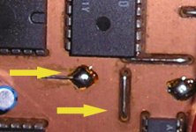
Griplet
before I started reading about Philips CD players I had never heard the word griplet. I don't believe it is a word in English. It's some crazy Philips made-up word, though it does sound quite good. I'm sure in some language it is the word for the sound a frog makes. It's kind of a rivet which forms a mechanical link belween the top and bottom tracks. This is then sealed over with an ugly dome of solder.
I desoldered these, drilled a hole through the griplet, pushed a length of wire through, soldered this on both sides and repeated for every griplet on the board. It takes a while to do this for both boards, but it worked for me and apparently for many others too. Worth one more try ?
Henri - I'm sorry that you have had such a frustrating experience, but you still have a positive outlook. If it's any consolation I managed to stick a cross head screw driver through the rubber surround on one of my Tangband W3-871s speakers yesterday, I hope I can use this experience as a lesson , as you have done.
Re: Griplet
Hi Andy and Jonathan,
Thank you for these two messages. I don't know if I will buy one on Ebay, that's more complicated than it seems. According to the law, I can buy there but I'm not sure my parents will agree if I buy a 21 years-old machine, with 30 Euros shipping charges at least lol! Maybe, if my cd104 dies completely, I'll buy another one, but it wouldn't be reasonable yet.
I was quite disappointed yesterday, that's right. But after 5 years, I'm used to it. That's not the first time I check something inside and ask myself if it will restart after. It has always restarted, despite all the stupid things I've done on the servo board. The worst was 3 years ago (at that time of the year actually!): I had no service manual at that time and I had decided to check the ICs one by one. I've desoldered the focus IC and destroyed both the prints and a few smd components. I've waited until dec 2003, bought the service manual on the Internet, repaired the prints and used ordinary resistors. I couldn't believe my eyes when I saw the focus working normally! I remember I've used it for 1 month (switched on al the time) this 2003 Christmas.
I'll retry the griplets trick (Is it what stands on the picture?) next weekend. Your messages are quite stimulating and helpful 🙂
Jonathan,
I'm very sorry to hear what happend to you yesterday 🙁 . I've also done many things like that, the CD104 adventure being one amongst the others. Big errors happen when we have to do things to quickly... 2 years ago I've wasted my chances to repair a Technics SLP110 cd player. On this player too, the disc was spinning too slowly, but unlike the CD104, the disc spins until the player is able to read it (mine was even able to find the TOC, and if I had waited, I'm sure it would have worked after a few hours of warming-up). But I wished to see quickly what was wrong and had about 30 min before dinner. I've removed the whole mechanism several times so as to access caps that were under it. I wanted to check the last one, removed the mechanism... without unplugging the flexiwire of the pick-up. Flexiwire half torn. Impossible to fix. I've spent hours so as to try to repair that flexiwire, for nothing. I haven't get rid of the SLP110 though, because the mechanism is fascinating (linear magnetic system, brushless motor) and I hope to find another pick-up one day .
Sorry to have been so long. But if It can help you to forget your bad experience.
Henri
poynton said:Hi.
Buy another one rather than the boards.
Fault finding is always easier that way.
Good luck !
Andy
jives11 said:before I started reading about Philips CD players I had never heard the word griplet. I don't believe it is a word in English. It's some crazy Philips made-up word, though it does sound quite good. I'm sure in some language it is the word for the sound a frog makes. It's kind of a rivet which forms a mechanical link belween the top and bottom tracks. This is then sealed over with an ugly dome of solder.
I desoldered these, drilled a hole through the griplet, pushed a length of wire through, soldered this on both sides and repeated for every griplet on the board. It takes a while to do this for both boards, but it worked for me and apparently for many others too. Worth one more try ?
Henri - I'm sorry that you have had such a frustrating experience, but you still have a positive outlook. If it's any consolation I managed to stick a cross head screw driver through the rubber surround on one of my Tangband W3-871s speakers yesterday, I hope I can use this experience as a lesson , as you have done.
Attachments
Hi Jonathan,
So, if I understand well, I must put a thin part of wire in each hole, even if that hole is not linked to a component/is empty? It's worth a try, yes!
Henri
So, if I understand well, I must put a thin part of wire in each hole, even if that hole is not linked to a component/is empty? It's worth a try, yes!
Henri
henri_85 said:Hi Jonathan,
So, if I understand well, I must put a thin part of wire in each hole, even if that hole is not linked to a component/is empty? It's worth a try, yes!
Henri
yes - your understanding is correct. Some griplets simply connect the copper ground on one side to an earth point on the other. It's important to do all, even if you meter tells you you have a ground in one place.
Hi Jonathan and Andy,
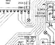
I've done as you've said... Et Resurrexit! I can't believe my eyes!! You can't imagine how happy I am 🙂. I had never noticed these griplets before. I thought they were just not used prints, and I didn't take care of the crosses on the shematics. Even if that was a matter of vocabulary, I also have to apologize for my scepticism. But now, I do agree: that solder-made griplets system is a bit stupid. Why didn't they put a wire in the holes??
So, many many thanks!!
Henri
henri_85 said:Hi Jonathan and Andy,
Et Resurrexit!
Bonsoir et Félicitations Henri,
you must excuse a humble Anglo-Saxon 😉 but my latin is non-existant.
Do you mean the player is now working ?
I do hope so, after all your efforts. I think you need to turn off the player and see if it works from cold in the morning to be sure. If it is working I'm very happy for you. Have a glass of Cidre to celebrate.
I too had a good day, I managed to repair the hole in my speaker rubber, using a bicycle puncture repair kit. I just used the liquid rubber adhesive. It seems to work.
henri_85 said:
But now, I do agree: that solder-made griplets system is a bit stupid. Why didn't they put a wire in the holes??
So, many many thanks!!
Things change after twenty years. Solder oxidises, dry joints form,flux leeches. It would not surprise me to find that these griplets are older than you and you've had constant maintenance.
Hi!
Jonathan,
Yes, I meant it works now!! There is no doubt about it. The griplets were the culprits, and when I looked at them carefully that was obvious. But alone I would never had noticed and understood their important role. My friend who gave it to me won't believe me!!
I'm glad you too repaired your speaker. I've looked on the Internet and understood how disappointed you were...!
Don't worry about latin, my knowledges are also fairly low 😀 . That was just for fun. Thank you, once again!
rfbrw,
Indeed, the machine and the solder are older than I am. I'm surprised that philips didn't think of that risk. I've seen these griplets don't exist on the next generation(CD150), and seem not to exist on the previous generation ( as far as I know, the CD100, 202, 303 don't have a copperfoil on their main PCBs).
Henri
jives11 said:
Bonsoir et Félicitations Henri,
you must excuse a humble Anglo-Saxon 😉 but my latin is non-existant.
Do you mean the player is now working ?
I do hope so, after all your efforts. I think you need to turn off the player and see if it works from cold in the morning to be sure. If it is working I'm very happy for you. Have a glass of Cidre to celebrate.
I too had a good day, I managed to repair the hole in my speaker rubber, using a bicycle puncture repair kit. I just used the liquid rubber adhesive. It seems to work.
rfbrw said:
Things change after twenty years. Solder oxidises, dry joints form,flux leeches. It would not surprise me to find that these griplets are older than you and you've had constant maintenance.
PSU
Hi!
My problems with the CD104 are not completely finished. Yesterday, I noticed the sound was a bit distorted (sounded a bit like when playing a tired LP). I've changed all caps on the servo, laser pre-amp and decoder boards (except the old axial Philips that are very reliable). The only originals remaining were the old Nichicons in the PSU. I've changed them and now it sounds fine. But I've used what I had in stock. For the 1500 at 1000µF, I used 2 Lelons caps (no choice yet), and for the two 3300µf, I only had 2 Hitano caps. I've searched a bit in all the mess though and found two second-hand 4700µF (a Nichicon VR and a standard Rubycon which has been used only a few hours). So I would like to know if I should use those two 4700 caps instead of the Hitanos. Increasing the values will it modify the voltages of the PSU, or make the regulators work harder?
Henri
Re: PSU
Hi.
Increasing the values of the caps will not increase the voltages.
It is sometimes better to increase the value after the rectifiers - this will not affect the way the regulators work.
As for the value of caps. after the regulators, there has been a difference of opinion as to the optimum value and type. Read the spec. sheet for the regulators. There is always a minimum value ! Some people say that increasing the value slows down the regulator as it sees the cap. not the load. Usually, going to the next larger value will not have any effect.
Andy
henri_85 said:
Increasing the values will it modify the voltages of the PSU, or make the regulators work harder?
Henri
Hi.
Increasing the values of the caps will not increase the voltages.
It is sometimes better to increase the value after the rectifiers - this will not affect the way the regulators work.
As for the value of caps. after the regulators, there has been a difference of opinion as to the optimum value and type. Read the spec. sheet for the regulators. There is always a minimum value ! Some people say that increasing the value slows down the regulator as it sees the cap. not the load. Usually, going to the next larger value will not have any effect.
Andy
Thank you Andy,
I've tried not to modify too much what Philips did. I was curious to know why they chose certain values (e.g 33µF for all the caps after the regulators) and if changing them would generate a modification in the voltages. But if it doesn't matter, that's a good thing.
And do you have an opinion about the type/brand of caps I should use. Unfortunately it's not very easy to find good caps here (you only get the Chinese things they sell, no choice), but I have some second-hand caps (Nippon Chemicon, Elna, Nichicon, Jamicon, Matsushita...) not too old. But yet I use the newer Hitano (http://www.hitano.com.tw/electrolytic.html) and Lelon (http://www.lelon.com.tw/) ones That's not a matter of "pride" or snobism, but a matter of reliability. I've seen what bad caps can do in a TV set and I would be sorry if the precious ICs of the decoder or the very rare microcontroler were killed because of a bad cap.
Henri
henri_85 said:Thank you Andy,
I've tried not to modify too much what Philips did. I was curious to know why they chose certain values (e.g 33µF for all the caps after the regulators) and if changing them would generate a modification in the voltages. But if it doesn't matter, that's a good thing.
And do you have an opinion about the type/brand of caps I should use. Unfortunately it's not very easy to find good caps here (you only get the Chinese things they sell, no choice), but I have some second-hand caps (Nippon Chemicon, Elna, Nichicon, Jamicon, Matsushita...) not too old. But yet I use the newer Hitano (http://www.hitano.com.tw/electrolytic.html) and Lelon (http://www.lelon.com.tw/) ones That's not a matter of "pride" or snobism, but a matter of reliability. I've seen what bad caps can do in a TV set and I would be sorry if the precious ICs of the decoder or the very rare microcontroler were killed because of a bad cap.
Henri
The standard answer to 'Which Cap.?' is Black Gate !
I use Panasonic ZL which are very good.
Marantz use Elna Cerafine for their high-end players.
It's up to you really.
If you can detect a difference !
Andy
- Home
- Source & Line
- Digital Source
- Philips CD104 tweaks