henri_85 said:Hi Philippe,
Thank you for the suggestion! I've just opened the beast, and switched the power supply (alone) on. And there is indeed a weird problem with the +5v regulator (n°6451). I have 10 volts on pin 1, and a decreasing voltage on pin 3, oscillating between 3 and 4.5 volts. Usually, when you switch on a power supply without consumption, the tensions are higher that those written on the shematics, so I suppose there is something wrong... Back to that part of the circuit. I've measured the tension on the 2452 cap, that is before this regulator, but it looks normal (around 20V). I've changed the regulator with a second hand one, but the decreasing tension is still present, instead of the normal 5V. I'll try to change the 2452 cap after dinner. I'm not used a lot to electronic diagnostics, so if you have another idea... 😉
Thanks again for your attention,
Henri
Hi.
6451 is the +12v regulator.
6456 is the +5v regulator.
Do you have the manual ?
Andy
Attachments
Hi again Philippe,
Nope, sadly I think the PSU works perfectly. I measured too quickly (I knew I had to do it very fast and it didn't help to concentrate and do things seriously). The regulators seems to be all ok. It's too late tonight, but I may retry to check those voltages. Sorry for that absurd mistake...
Henri
Nope, sadly I think the PSU works perfectly. I measured too quickly (I knew I had to do it very fast and it didn't help to concentrate and do things seriously). The regulators seems to be all ok. It's too late tonight, but I may retry to check those voltages. Sorry for that absurd mistake...
Henri
Hi Andy,
I'm sorry, I mixed up everything. Had to do all that so quickly. Yes, I have the manual (by the way, it seems that everyone on the Internet owns the same copy ). I fear this fault is a very rare one and can't be cured. I hope it won't give nightmares to all CD104 owners!
Best wishes,
Henri
🙂 🙂 🙂
I'm sorry, I mixed up everything. Had to do all that so quickly. Yes, I have the manual (by the way, it seems that everyone on the Internet owns the same copy ). I fear this fault is a very rare one and can't be cured. I hope it won't give nightmares to all CD104 owners!
Best wishes,
Henri
poynton said:
Hi.
6451 is the +12v regulator.
6456 is the +5v regulator.
Do you have the manual ?
Andy
🙂 🙂 🙂
Hi andy and Philippe,
One last post about that stupid fault. I've checked the PSU voltages once again and everything is normal 🙄 . So the fault must come from a bad MCES, or from the turntable servo section. I hope I'll find a scope to check the MCES. But if it is in the turntable servo, I really don't know what can be the cause of the problem. There are tensions that are indeed much lower than what they should be. I just know it's not a cap, it's not the BC635 & 636 , not the MC1458 and not the BZV46 diodes...
But thank you for your help, now I know its power supply almost by hearth 🙂
Henri
Hi Andy,
Yes, I think I have done all of them. I should maybe check them once again, but I'm not optimistic. If that was a griplets problem, I guess the fault would be unpredictable. It's not the case though. But thank you for the advice. Did you encounter the griplets fault, and how was it exactly?
Henri
Yes, I think I have done all of them. I should maybe check them once again, but I'm not optimistic. If that was a griplets problem, I guess the fault would be unpredictable. It's not the case though. But thank you for the advice. Did you encounter the griplets fault, and how was it exactly?
Henri
henri_85 said:Hi Andy,
Did you encounter the griplets fault, ......?
Henri
Several times !!!!!!!
All different.
Andy
Hi,
I've restarted my CD104 today (not only the PSU, this time). After the usual 15 min 30 min of "warming up", It played CDs perfectly again. I haven't heard ant annoying noise this time (yet...), that's maybe because I've let it sleep 2 or 3 weeks before restarting it.
But I have another question. On this CD104, it has always been difficult to read CDRs and CD that were longer than 73 min (but it depends on the CD). I've noticed that if I turn (not clockwise) the turntable height screw (under the rotor), it was possible to read 79 min CDs, and it improved its CDR reading "skills". The big disadvantage of this though is that the turntable can't start by itself very often. It can be understood: the coils are maybe too far from the rotor. If I turn the screw clockwise, it becomes very difficult to play long CDs and CDRs, but the turntable starts without help almost each time. I should maybe lubrificate the motor, so what type of oil should I use? And is there something to adjust on the laser amp PCB?
Henri
henri_85 said:Hi,
I've restarted my CD104 today (not only the PSU, this time). After the usual 15 min 30 min of "warming up", It played CDs perfectly again. I haven't heard ant annoying noise this time (yet...), that's maybe because I've let it sleep 2 or 3 weeks before restarting it.
But I have another question. On this CD104, it has always been difficult to read CDRs and CD that were longer than 73 min (but it depends on the CD). I've noticed that if I turn (not clockwise) the turntable height screw (under the rotor), it was possible to read 79 min CDs, and it improved its CDR reading "skills". The big disadvantage of this though is that the turntable can't start by itself very often. It can be understood: the coils are maybe too far from the rotor. If I turn the screw clockwise, it becomes very difficult to play long CDs and CDRs, but the turntable starts without help almost each time. I should maybe lubrificate the motor, so what type of oil should I use? And is there something to adjust on the laser amp PCB?
Henri
Dear Henri (there is a hole in the bucket)
Service laser
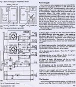
1 Play a cd.
2 connect a voltmeter over resistor 3308 to ground.
3 adjust with resistor (turnpot) 3180 the voltage on the
voltmeter to about 500 mV (plus minus 50 mV) ( > 550 mV will
damage the laser.
The manual sais something about a newer laser type
(with a red painting dot on it) that have to be adjusted
to 560 mV plus minus 50 mv.
resistor 3308 resides on the servo PCB
resistor 3180 (turnpot) on the pre.amp laser PCB.
I have the original manual in Dutch. (not English !!)
You know perhaps that you can play a cd
with the machine (CD104) upside down.
first load a cd than turn it upside down and don't eject !!
That's handy to reach the turnpot.
If you want more info pse ask.
succes
Onno
Hi Onno,
Thank you for the advices. So you think it's a laser voltage matter?... And the height of the turntable isn't important?
Hmm there are 3 turnpots on the pre-amp laser PCB. Which one must I adjust?
Even if your (CDM1, isn't it?) manual is in Dutch, I would be interested in it. Dutch looks a bit like german and english mixed together 🙂 .
A bit off-topic: does anyone have the CDM2 manual?
Thank you for your help,
Henri
henri_85 said:Hi Onno,
Thank you for the advices. So you think it's a laser voltage matter?... And the height of the turntable isn't important?
Hmm there are 3 turnpots on the pre-amp laser PCB. Which one must I adjust?
Even if your (CDM1, isn't it?) manual is in Dutch, I would be interested in it. Dutch looks a bit like german and english mixed together 🙂 .
A bit off-topic: does anyone have the CDM2 manual?
Thank you for your help,
Henri
Dear Henri,
NO, I think the turntable height is not the culprit.
The laser PBC has 3 trimpots
2 more in the middle and 1 more at the (longest) side
It's the one on the side.
For the service manual.
I think that the english version is OK and that version is available
on the web.
If this will solve your problem I do not know OC ! But there is a good chance.
In your post you mentioned that you have to wait for 15 minutes or 30 minutes until the player reads the cd.
To solve that you have to rewire al the grippets on the servo PCB.
What I did is drilling holes and put a wire through it.
Further I resoldered ALL soldered points on all the PBC's
including IC's and SMD parts.
That cost a lot of time (for me FI about one hour for the servo PBC)
Onno
Hi Onno,
I've tried to adjust the laser voltage this morning. Unfortunately it was already correct (500 mV exactly)... There are certainly other problems. Maybe the weird "original" fault (see my previous posts for the whole story). The poor condition of the servo board (after hours of search, soldering and unsoldering caps, ICs, diodes...) probably doesn't help, but both the original problem and the long CD/ CDR low-reading "skills" were present when I got the machine. lol I should post a photo of that servo board, it would make you giggle for the rest of the day 😀.
Anyway, thank you for the adjusting method ,
Henri
Hi!
Something unusual happend to my CD104 this afternoon.I had started it yesterday morning. After the warming up, everything worked fine. This afternoon, the motor crashed, whereas it never did it in the past. Indeed the motor voltage is around 0.1 V now... The fact it occured after more than 24 hours of "work" is quite new. It would mean the griplets are maybe the culprits...? I have a question about the well-known griplets fault. What happens, in your opinion, when they fail? Is it an electrical-chemical phenomenon???
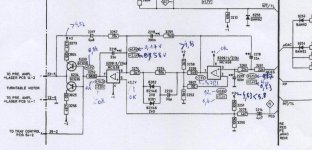
I've added the relevant part of the shematics, with the voltages I've measured. What do you think of it? (sorry, it's not very clean. If something is unclear(!) please ask me).
See you,
Henri
Something unusual happend to my CD104 this afternoon.I had started it yesterday morning. After the warming up, everything worked fine. This afternoon, the motor crashed, whereas it never did it in the past. Indeed the motor voltage is around 0.1 V now... The fact it occured after more than 24 hours of "work" is quite new. It would mean the griplets are maybe the culprits...? I have a question about the well-known griplets fault. What happens, in your opinion, when they fail? Is it an electrical-chemical phenomenon???
I've added the relevant part of the shematics, with the voltages I've measured. What do you think of it? (sorry, it's not very clean. If something is unclear(!) please ask me).
See you,
Henri
Attachments
Hi.
Poor build quality !! You must remove the old solder and drill out the griplet with a very small drill. solder a copper wire from the top to the bottom of the board ensuring a very good joint.
The voltages look OK. (minor value changes could be the meter you are using)
What are the voltages at the outputs of all the regulators??
Andy
henri_85 said:I have a question about the well-known griplets fault. What happens, in your opinion, when they fail? Is it an electrical-chemical phenomenon???
Poor build quality !! You must remove the old solder and drill out the griplet with a very small drill. solder a copper wire from the top to the bottom of the board ensuring a very good joint.
I've added the relevant part of the shematics, with the voltages I've measured. What do you think of it?
The voltages look OK. (minor value changes could be the meter you are using)
What are the voltages at the outputs of all the regulators??
Andy
Hi Andy!
The voltages at the outputs of the regulators and on every pin of the PSU are normal. The problem must be somewhere on the servo PCB, I guess.
Now you've convinced me! I'll remove all the old sticky solder. I'll see what I can do with the small drill though, because I'm afraid of damaging the prints. If it's not the solution, then I don't know what to do 🙁 . I'll do it next weekend (homework waiting for me). Thank you for you help, it gives me some hope 🙂.
Henri
Hi Henri,
I had similar symptoms with my CD 304 when installing a Kwak Clock, the disc spun very slowly. I managed to trace it to a bad ground at the SAA7000 chip. Secure grounding of the clock (crystal SMD caps in your case) resolved it.
If you have a look near the SAA7000 the 2 SMD caps of the crystal are grounded to a griplet linking them to the PCB ground plane. Try removing all the solder at this point, then resolder with wire as per Andy’s suggestion. I found ‘Goot’ solder wick to be excellent, you could also use the tip of a compass to widen the hole after desoldering.
You also said that you replaced all caps, have you done the light orange solid Alu Philips electrolytic caps 33uF, 10uF, 1uf & 6.8uF caps on the servo board? And the caps on the CDM’s board.
If that dosn't work, it may be the TCA240 chip on the servo board. You will need to get the same chip, not the C, D versions.
cheers
Rich
- Home
- Source & Line
- Digital Source
- Philips CD104 tweaks