I am very tempted to comment on chemists vs engineers but that sort of debate has got me into trouble so I will have to remain just tempted.
Says the physicist.
If there's sufficient difference in the Miller effect between two output triodes to cause an issue, the cathodyne is the least of one's worries! Jones's suggestion was to load both outputs with a higher capacitance to swamp out any such variations. The low source impedances of the two ports with a high gm tube allows this to be done without much consequence.
Burkhardt Vogel's analysis has now been posted at Linear Audio's site. When I have more time next week, I'll respond to a couple of points that he brought up.
Linear Audio | Letters
Linear Audio | Letters
Right way: keep balance while measuring. I.e. measure impedances loading both outputs equally. Otherwise what you measure is not a Concertina anymore, since it is unbalanced by your measurement tools.
Except that by doing that, you're not measuring the single-ended output impedances. This is elementary, isn't it?
Except that by doing that, you're not measuring the single-ended output impedances. This is elementary, isn't it?
Do you mean unbalanced output impedance? It is meaningless. What's the purpose of a phase splitter if only one output is used?
I would rather add some new term to measure Concertina that would reflect sensitivity of it's amplification factor to the load of an opposite output. It would be very asymmetrical, of course. But it is incorrect to translate such sensitivity to load difference to the output resistance.
Glancing over Burkhard's analysis, I still must return to my point about this circuit, that if indeed it is a good unbalanced to balanced converter as is asserted, it should serve as a good balanced line driver. It does not, because there is a strong transmission term from the cathode to the anode, and a small one from anode to cathode. Folks, this is not something that should be conflated with the measurement of impedances.
In order to treat this circuit in a truly rigorous fashion one needs to really understand the theory of n-ports. To recall, in such analysis we don't even identify ports as inputs or outputs but treat them as ports that are loaded or not, driven or not. And when you add even just one port the amount of complexity goes up significantly. We have here a three-port, and our work is cut out for us. If I have the time I will work this out, but it is a job.
Now, the tendency for those of us who are familiar with simple circuits is to say Oh well it's obvious that this is the input, and that there will hardly be any effect if we stimulate this other terminals, and this terminal is clearly an output.... But there is some effect in each case.
Again I must remind: balanced does not mean equal and opposite voltages. It means equal impedances to common. In that sense a balanced line circuit is really a three-wire one. Driven separately as an external excitation, the Cathodyne has widely different impedances at plate and cathode. Jones misapplies feedback theory in the 3rd edition, and as pointed out by Paul, essentially contradicts himself within the space of a few pages. Stuart claims that drive with two identical polarity current sources is unequal loading (I haven't yet read the details, although I have the issue).
This all should not be that difficult. And all camps agree on the equal output voltage magnitudes under equal loading. The circuit behavior is not the issue under those conditions.
I communicated privately with another LA author after his article appeared, because it contained a section related to this cathodyne controversy that I felt was misleading. As it was a private communcation I cannot at the moment reproduce it here. But he agreed with my point made and mentioned that it would be addressed in a followup, and his comment about the problem was couched in the language of network theory, and expressed the term that corresponds to the transmission from the (equivalent) cathode to the (equivalent) anode.
Brad Wood
Do you mean unbalanced output impedance? It is meaningless. What's the purpose of a phase splitter if only one output is used?
The "unbalanced" output impedance may not be a useful measure in this application but it certainly isn't meaningless. Moreover, it is what it is regardless of how the circuit is used.
Conceptually though, it's quite simple isn't it? Conceptually, and working in the small-signal domain, zero the input source(s) and connect a small-signal test current source to both outputs of the phase splitter. Label the one connected to the plate node Itp and the other Itk.
Then, the (phasor) voltage at the plate node is:
Vp = Zp * Itp + Zkp * Itk
where Zp is the impedance looking into the plate node and Zkp is the transfer impedance from cathode to plate.
Likewise, the voltage at the cathode node is:
Vk = Zk * Itk + Zpk * Itp
where Zk is the impedance looking into the cathode node and Zpk is the transfer impedance from plate to cathode.
Clearly, to directly measure Zp, Itk must be set to zero and to directly measure Zk, Itp must be set to zero.
In the special case that Itp = -Itk, the impedance seen at the plate node is:
Vp / Itp = Zp - Zkp
And, at the cathode node:
Vk / Itp = Zpk - Zk
These values may very well be equal, i.e., Zp - Zkp = Zpk - Zk but that doesn't imply that Zp and Zk are equal.
Besides, off the top of my head, I suspect that Zp and Zk are in fact useful measures in that they are related to the sensitivity of each node to unbalanced loads.
These values may very well be equal, i.e., Zp - Zkp = Zpk - Zk but that doesn't imply that Zp and Zk are equal.
Besides, off the top of my head, I suspect that Zp and Zk are in fact useful measures in that they are related to the sensitivity of each node to unbalanced loads.
Demonstrating the sensitivity of the asymmetry of the cathodyne's outputs to measurement technique. I think we're *really really* ready for your earlier suggestion that we discuss common mode and differential mode impedances.
You go first!
Thanks,
Chris

Rather than looking at the math why not simply build and measure it. Spice makes it quite simple. There are a couple of accepted ways to measure output impedance floating around and they are all essentially the same thing. Since there seems to be confusion about currents flowing to ground and not in a loop I hope the way the circuits are drawn make the loops clear. Also since the statement was made that shorting the ouput gives no signal I'll use two other accepted methods of measuring output impedance.
The first is measuring the output in an unloaded situation and then loading the circuit until the output is 1/2 (-6dB). On a whim I used 82.33 ohms and guess what. (see screen grab.)
The second method takes the output voltage of an unloaded circuit and the output voltage of a loaded circuit and applies the formula Zo=((VVload)*Rload)/Vload. as shown in the other image I used a load of 1000 ohms and used he cursors to measure 1.87 for V and 1.73 for Vload so Zo=((1.87-1.73)*1000)/1.73 which comes to 81 ohms.
Now before anyone squawks that the number do not match, I'll admit I did not of precisely placed the cursors and rounded the numbers to two decimals so being off by a few percent isn't too alarming.
dave
dave
The first is measuring the output in an unloaded situation and then loading the circuit until the output is 1/2 (-6dB). On a whim I used 82.33 ohms and guess what. (see screen grab.)
An externally hosted image should be here but it was not working when we last tested it.
The second method takes the output voltage of an unloaded circuit and the output voltage of a loaded circuit and applies the formula Zo=((VVload)*Rload)/Vload. as shown in the other image I used a load of 1000 ohms and used he cursors to measure 1.87 for V and 1.73 for Vload so Zo=((1.87-1.73)*1000)/1.73 which comes to 81 ohms.
An externally hosted image should be here but it was not working when we last tested it.
Now before anyone squawks that the number do not match, I'll admit I did not of precisely placed the cursors and rounded the numbers to two decimals so being off by a few percent isn't too alarming.
dave
dave
Also since the statement was made that shorting the ouput gives no signal...
But it does. Current, just as much a signal as voltage. After all, when we measure voltage, ideally the current is zero.
... there is a strong transmission term from the cathode to the anode, and a small one from anode to cathode. Folks, this is not something that should be conflated with the measurement of impedances.
Exactly. That's why it is more productive in this particular case to measure interdependence of amplification factors of outputs on each other loads than their output impedances. If we measure dV on one side caused by dR on an opposite side it does not mean we are getting dI. It is something else, though more valuable than that.
Last edited:
But it does. Current, just as much a signal as voltage. After all, when we measure voltage, ideally the current is zero.
Hey,
I didn't make the statement. In thinking about it, doesn't spice simply use math to solve everything? In order to dispute the results you either need to point to a flaw in my methodology or accuse spice of using the wrong math.
dave
You can only talk about yourself , and leave the majority of the others to speak about themselves , i said in post 111 that if we change the 2 loads with 2 others harder loads , and i mean equal ones , then measure the two output voltages and you will find that the anode voltage is lower than that of the cathode . And one question , do you agree with my comments about the output impedances of the Concertina in the same post ? , Yes or No and why ? .You can't say that. Because doing measurements changing loads separately you disbalance Concertina, so it is not a Concertina anymore. Try to change both loads at once, equally, to keep it balanced, and calculate both resistances separately.
Edit: What is remarkable, chemist SY understands electronics better than the majority on this forum, including many Electrical Engineers. What is so special in chemical education, so it so superior to education of Engineers? 😉
Harder loads i mean the grids of 2 or maby 4 EL34 , compared to the grids of EL84 for example .
... i said in post 111 that if we change the 2 loads with 2 others harder loads , and i mean equal ones , then measure the two output voltages and you will find that the anode voltage is lower than that of the cathode .
No, exactly the opposite, they both change, and change equally as demonstrated experimentally in my article. I used capacitances FAR higher than the grid capacitance of 4 EL34.
The problem is in definition of "hardness" of load. If you use linear loads voltages will be the same, since no matter what is resistance of equal loads, it is equal. But if you drive non-linear loads, it will be of course unequal.
Edit: I forgot about one more case when voltages will be equal even when both outputs are loaded on non-linear loads. But you will need a couple of complementary output tubes to do that. Unfortunately they can't be made, because tubes of P - type have enormous sizes, so very different properties. 😉
Edit: I forgot about one more case when voltages will be equal even when both outputs are loaded on non-linear loads. But you will need a couple of complementary output tubes to do that. Unfortunately they can't be made, because tubes of P - type have enormous sizes, so very different properties. 😉
Last edited:
The problem is in definition of "hardness" of load. If you use linear loads voltages will be the same, since no matter what is resistance of equal loads, it is equal. But if you drive non-linear loads, it will be of course unequal.
What put me down this path some 20 years ago was, coincidentally, an EL34 amp driven by a cathodyne. I compensated the cathode side and got terrible results. After reading Crowhurst's "Understanding Hifi Circuits" and not believing him about the cathodyne balance, I measured it myself with a scope and got unbalanced results. Now, I've caught mistakes in Crowhurst before but not often, so I spent a day or two thinking about it and where I could have gone wrong. Just for giggles, I used both channels of my scope and looked at both outputs at once. I think you know the result, it was perfectly balanced and boy did I feel stupid.
Another name of Concertina is Split-Load phase splitter. I.e. cathode load resistor of a cathode follower split in half, and one half moved all the way through power supply to anode.
What put me down this path some 20 years ago was, coincidentally, an EL34 amp driven by a cathodyne.
The reason I bought the August 2011 AudioXpress, was for the ECC99 concertina driven EL34's article. Thought I might try this with 6N6P's driving 6P3S-E's
jeff
Once you add buffers, unequal impedance due to grid current is hidden. This is the
obvious soloution to both problems. Concertina with equal impedance split does not
by itself solve anything...
Exactly.
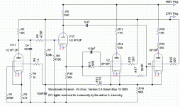
Here is my example. It drove GU-50 outputs with 240K parallel feedback resistors from their anodes, pretty tough load.
Attachments
- Home
- Amplifiers
- Tubes / Valves
- phase splitter issue