Think about the circuit with the 330k missing. Then the cathodyne cathode and anode resistors must be the same value (for AC balance) and so will have the same DC voltage drop. The DC drop across the cathode resistor is set by the anode voltage of the previous stage, so roughly 100V. The anode resistor has to drop 100V too, so the cathodyne valve has only 'supply rail - 200V' to work within. This is insufficient for adequate signal voltage swing.
So put the 330k back in. This reduces the valve current and so reduces the DC drop across the anode resistor. Furthermore, the 330k has reduced the AC resistance seen at the cathode because for AC it appears in parallel with the cathode resistor. Hence the anode resistor has to be dropped in value too so that it matches - this gives a further increase in cathodyne anode voltage. So now the PS has more room to work in.
An alternative could have been to reduce the anode voltage on the previous stage, but then it would have insufficient room to work in.
In engineering terms a better solution would be to raise the supply rail voltage, but they may have had reasons not to do this.
The 330k makes little difference to arcing; the solution for that is either a diode or a small neon lamp across the grid-cathode of the cathodyne.
Yeah, I can see your point. Looking at CPaul's load lines, it is clear that the 330k case creates more usable range of operation through the range of adjustment.
It seems I was a bit hasty in removing the resistor in my amp. I'm thinking that the solution in my amp will be a mosfet phase splitter which has no grid-current no-man's land. That should recover a lot of swing (and create more) even in the face of the DC conditions here.
It seems I was a bit hasty in removing the resistor in my amp. I'm thinking that the solution in my amp will be a mosfet phase splitter which has no grid-current no-man's land. That should recover a lot of swing (and create more) even in the face of the DC conditions here.
The 330k resistor does give us a more usable range of operation given the existence of the R83 pot. But it's like putting a band aide on a deep wound.
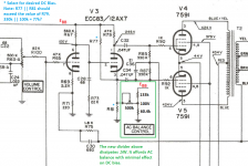
Let's forget the question of supply noise cancellation addressed in Post 1094 and address the need for AC balance. The right solution is to put the R83 pot in series with a large capacitor and a fixed limiting resistor. Tie the bottom of R81 to ground and select an appropriate value for it. Get rid of the 330K resistor. Now you have optimal bias, completely unaffected by the AC balance setting.
Having the AC balance affect the DC bias is a bad design practice.
They should not need a pot to get good AC balance and correct DC bias; a calculator would do the job more cheaply. The extra (330k) resistor may be unavoidable given a low supply rail voltage. What they should have done is have the 330k feeding the cathode resistor (as they have) but then put 330k in parallel with the anode resistor (equal in value to the cathode resistor). Then both cathode and anode see 330K in parallel with the load resistor, so AC balance is guaranteed with nothing to adjust. Scrap the pot.
They should not need a pot to get good AC balance and correct DC bias; a calculator would do the job more cheaply. The extra (330k) resistor may be unavoidable given a low supply rail voltage. What they should have done is have the 330k feeding the cathode resistor (as they have) but then put 330k in parallel with the anode resistor (equal in value to the cathode resistor). Then both cathode and anode see 330K in parallel with the load resistor, so AC balance is guaranteed with nothing to adjust. Scrap the pot.
The purpose for the pot is not to ensure a balanced output on the cathodyne, it is to make it possible to purposely introduce imbalance to compensate for gain imbalances in the output tubes. Proper adjustment procedure (according to the service manual) is to connect the amplifier to a distortion analyzer and adjust the AC balance pot for minimum distortion. It is a system-level design choice, but definitely not a user-friendly design choice.
Agreed, SpreadSpectrum.
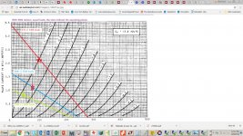
And DF96 & SpreadSpectrum, check out the two sets of operating points, one with and one without the 330k resistor, both with identical plate and cathode loads.
DF96's proposal with matched plate and cathode loads: Leaving the 330k resistor makes matters worse!
And DF96 & SpreadSpectrum, check out the two sets of operating points, one with and one without the 330k resistor, both with identical plate and cathode loads.
DF96's proposal with matched plate and cathode loads: Leaving the 330k resistor makes matters worse!
Attachments
Keep in mind that the cathodyne is a self balancing device.
It will seek a middle operation point which might differ from your calculations.
SpreadSpectrum could probe some voltages on his amp before he scraps the whole tube and insert a transistor.
R83 properly set can absolutely place this amplifier in another league of performance and reduce considerably the distortions (-5 db in main harmonics was my experience with matched and individual bias output tubes)
Inserting a high value grid stop R will prevent the grid from drawing lot of current from the first tube anode. There is no need to add more 330k resistors
Can you explain "the Cathode is a self-balancing device?" It will somehow operate differently from what a load line analysis shows? How?
Yes, a larger grid stop resistor can limit the maximum grid current. But a triode biased to pass grid current will simply cause a larger voltage drop to occur across a high value grid stop R and will also change the bias condition, and probably in a not easy to predict manner. This is to say nothing of whether grid current will increase distortion, with or without the grid stop resistor.
Yes, a larger grid stop resistor can limit the maximum grid current. But a triode biased to pass grid current will simply cause a larger voltage drop to occur across a high value grid stop R and will also change the bias condition, and probably in a not easy to predict manner. This is to say nothing of whether grid current will increase distortion, with or without the grid stop resistor.
So you are saying that they got it wrong - they don't need the 330k at all?CPaul said:DF96's proposal with matched plate and cathode loads: Leaving the 330k resistor makes matters worse!
I don't know why people are talking about grid current. If the cathodyne might pass grid current then they need to redesign this away. Usually the way to do this is to raise the anode-cathode voltage so the grid can be biased back more.
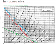
Here's what I get for the load lines with and without the 330K resistor and the operating points at the extreme settings of R83. Unless I miscalculated, a good portion of the pot range will lead to grid current being drawn. And in comparison to the pot settings, the effects of the 330k resistor seem small.
In my opinion, it should have been designed to preclude the possibility of grid current being drawn.
ecc83 was born in wrong era, it needs mosfet fellow to shine.
Let me just say that based on my analysis (which I invite anyone to review and criticize - I could have goofed), the 330k seems to have only a minor effect, but it is a deleterious one.
We must assume on average that the output stage is balanced, because even if it were unbalanced, to counter the unbalance, it's just as likely that the cathodyne's plate signal should be increased as that its cathode signal should be.
Accordingly, we should analyze with R83 adjusted for equal 47k loads seen by the cathodyne plate and cathode. The graphs in post 1186 show that in this case, the 330k resistor moves the grid bias less negative, from -0.5V to about 0V - definitely the wrong direction.
Also, at low frequencies, I calculate the common cathode gain stage driving the cathodyne to have a ground referenced impedance looking into the plate of about 320k. Working with its 560k load resistor as a voltage divider, this means that there is less than half of the supply noise at the gain stage's plate and at the cathodyne's grid and cathode. And so there is more than half of the supply noise at the cathodyne plate.
Simulations show that the addition of the 330k resistor does increase the noise contribution at the cathodyne's cathode as desired to improve the balance, but it also increases the one at its plate even more, leading to a net worsening of the unbalance in supply noise (which ideally should be equal.)
I vote to remove the 330k resistor.
I can't see how adding the 330k resistor moves the grid bias (more positive i.e. less negative) towards 0V.
Let's start by assuming that the previous anode is fixed (at 100V). Without the 330k the cathodyne (assume balanced) will settle with approximately 100V drop across the cathode resistor and 100V across the anode resistor. The grid bias will be whatever is needed to get the right current for this.
Now add the 330k resistor. This injects current into the cathode resistor, so the valve has to pass less current - this requires that the grid bias becomes more negative. This is helped by the 330k tending to pull up the cathode, although it can't pull very much. Also, the anode voltage of the cathodyne will rise so this means even more negative grid bias to maintain the (new) required current. Far from reducing the negative bias, the 330k increases it.
I can't see how adding the 330k resistor moves the grid bias (more positive i.e. less negative) towards 0V.
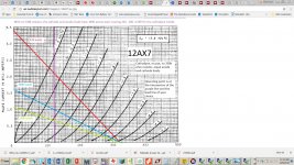
CPaul's graphic in post #1174 seems to show graphically that adding the 330k resistor shifts the idle conditions to a more negative range as well.
I think you are right about what the designer was after in this instance. He probably got a pat on the back from his boss for figuring out a way to make this all work without having to create another supply rail and not affecting performance in too negative a manner.
Curiously, I removed the 330k resistor in my amp and got rid of the AC balance pot and just put two 47k resistors on the cathodyne and it really doesn't sound bad (sounds quite nice, actually). However, I think it is probable that my +320V rail is running higher than nominal, so that may be why I don't have problems (or maybe I do have problems and I just don't turn it up enough to find out). The 7591 output tubes really don't require much swing to drive to clipping.
Next time I have the desire to get into this thing, I might just throw a mosfet into that position and clear up all issues here by permanently removing that Vg=0 barrier. I hate the idea that maybe my phase splitter is clipping before the output stage.
They say it takes a big man to admit he made a mistake. Well, I'm feeling pretty large right now. Please ignore post 1186.
Let me try again.
The setting of R83 has a big effect on the circuit. So when we analyze the Cathodyne, what shall we set it to? Well, to its average value. So what is that?
On average, the output stage is balanced - its weaker and stronger sides could be driven by either the Cathodyne's plate or cathode. So, let's always adjust R83 for equal and opposite cathodyne outputs - that is, ensure that the parallel combination of R77 (the 330k resistor) and the R83 pot + R81, is always equal to R79, the plate load resistor.
Looking the graph, the 330k resistor does indeed improve and make the grid bias more negative (red line and star operating point) than if the 330k were absent (blue line and star.)
However, the same grid voltage bias could be arrived at without the 330k R77 if the plate resistor R79 and (R83 + R81) were set to 120k.
Attachments
I haven't really been following the 330 ohm resistor controversy so I hope that isn't too annoying to everyone. I will say this though - it's very hard to get maximum theoretical signal output from the cathodyne for the given PS voltage going into it. The theoretical maximum signal output comes with the cathode load biased at 1/4 the supply voltage and the plate load biased at 3/4 the supply voltage. I've found that out in my own simulations.
Also, I've found in my simulations that the FFTs show a lot of higher harmonics in the output signal if the loads aren't biased exactly that way. My understanding is that is some interference between the signals in the two loads if they aren't biased that way. If the load resistors are biased at 1/4 and 3/4 power supply voltage then the signal is free of interference between each other right up to a signal input of 1/2 the power supply voltage. The FFTs show remarkably low to non-existent sidebands above the 4th or 5th harmonic if you keep the signal below that level. That is really why I said that the cathodyne "can" be a superior phase splitter to any other.
Also, I've found in my simulations that the FFTs show a lot of higher harmonics in the output signal if the loads aren't biased exactly that way. My understanding is that is some interference between the signals in the two loads if they aren't biased that way. If the load resistors are biased at 1/4 and 3/4 power supply voltage then the signal is free of interference between each other right up to a signal input of 1/2 the power supply voltage. The FFTs show remarkably low to non-existent sidebands above the 4th or 5th harmonic if you keep the signal below that level. That is really why I said that the cathodyne "can" be a superior phase splitter to any other.
Some of the caveats to getting all the potential out of a cathodyne involves doing things some people will not like. They don't bother me, but I'm not everyone!
1. Besides the obvious of keeping your loads equal, make sure there is never a chance that the following stage will draw grid current. For me that means a source follower as the next stage.
2. This is where people will object. I've never found a way to get the full potential out of a cathodyne for the PS voltage feeding when direct coupling it from the previous stage. I've tried every way I can think of in simulation and eventually I've just given up. I now capacitively couple them and use a high resistance voltage divider to bias the cathodyne. Then you can actually refine everything to a gnat's behind without having to worry about altering the balance between the two stages. In my view it far more important to bias the cathodyne loads at the 1/4 and 3/4 point than it is to direct couple. I've never been able to get that to work when direct coupling. Try simulating it yourself and watch the FFT as you move off that point.
how about running that front end on a higher B+ than the output stage? can you simulate it?
i have done SE amps with the front end with its own b+ supply than the output stage and liked the results....i make my own traffos btw, so i am able to do that...
i have done SE amps with the front end with its own b+ supply than the output stage and liked the results....i make my own traffos btw, so i am able to do that...
Yes, that should work. I actually was going that route until I decided that direct coupling just wasn't worth it to me. But you'll definitely get a higher potential output signal going that route, or lower distortion at higher voltages than before. I've simmed that too.
- Home
- Amplifiers
- Tubes / Valves
- phase splitter issue