If you want to drive A2 or AB2, use a FET source follower to buffer each output.
I know that. I was proving a point, that lack of equal Z was never the problem.
You can make a concertina of equal and exceptionally low Z, it still don't work.
Concertina can't drive DC without further buffering, so pointless to argue the
impedance mismatch scenario involving grid conductions. It fails for another
far more serious reason that has nothing to do with any mismatch of Z.
Hi Dave, I'm making good progress looking at your sim with the LCR (thanks for posting - saved me a lot of trouble and probably mistakes trying to enter it myself).
Do you have / can you post a spec or a URL for a spec for the LCR module?
Thanks.
Do you have / can you post a spec or a URL for a spec for the LCR module?
Thanks.
Dave and I are discussing what we can and cannot agree on. More to post soon once we sort this out.
Consensus is like unrequited love; so desirable, yet so difficult to consummate!
It’s a shame that the lights are out at Dave’s company and he has to work from the library. But one of Dave’s stated requirements had a role in this unfortunate event.
Most likely, he was misled by the Cathodyne model containing a pair of ground referenced, differential voltage sources in series with 1/gm (see Model 1 in subsequent sims). In accordance with that model, each LCR module, to meet its spec, requires its source to be padded so as to be driven from a total impedance of 6Kohms. But this requires the voltage-balanced (and not impedance-balanced) Cathodyne that we all know and love to be redesigned (see italics below). You don’t get something for nothing, and a consequence of the redesign was to unbalance the overall gains in the plate and cathode paths and lose, worst case, 1.7dB of RIAA accuracy at 20Hz in the plate path. Was that demand necessary or even desirable?
No. On both counts.
Remove the ground between the voltage sources in Model 1 to get Model 2 (see the sims again.). The combination of two LCR inputs in series is quite happy to be driven from this 12K impedance source. Can the traditional Cathodyne be looked at in this manner? It sure can! Take a look at sims of the Cathodyne and the two models shown below. You’ll see that the responses of the plate and cathode in all three circuits are identical.
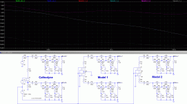
But now we face a conundrum. We know that both models perfectly and identically predict the Cathodyne output responses. But one states that the plate and cathode to ground impedances are about 1/gm, and the other that they are about Z/2 (where Z is the load seen looking out of the plate or the cathode.) So which is the correct model? We can’t tell from the available evidence. Our only option is to perform more tests.
Let’s measure the ground-referenced plate and cathode impedances in the Cathodyne and the two models. What better way is there to do that than by zeroing the ac grid voltage, connecting a ground-referenced ac current source to the plate, dividing the ac plate voltage by the current source’s current to get the plate impedance, and then repeating the process at the cathode? (This is not a rhetorical question. If you think you have a better way, let us in on it and justify your claim.) The results can be seen in the two sims below.
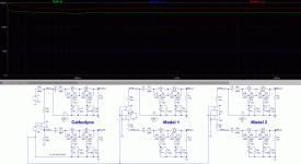
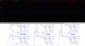
Clearly, neither of the models’ responses matches those of the Cathodyne. Nor do they match each other’s. If the only choice in predicting these impedances were one of the two models, we’d have no justification for preferring one over the other. But there is another possibility: both models are wrong! And that’s the conclusion fits the data.
So we now see the practical, real world consequence of accepting a bad model of the Cathodyne, even when we’re only dealing with the balanced situation to which it is supposedly perfectly suited. An unnecessary requirement is added to the design, resulting in a product that performed so badly that nobody wanted it!
We’d all do well to understand from these sims how the Cathodyne really works. Get these models out of your head! If you don’t, they could bite you when you least expect it. Just ask Dave and his company.
And yes, the Cathodyne sim reveals, of course, that its plate and cathode impedances are indeed different.
To go from a balanced voltage Cathodyne to a balanced impedance Cathodyne, change R41 to 682ohms and R29 to 6190ohms in all three sims. In the first sim, it is easiest to see the slightly imperfect RIAA match if you plot V(cath_out_+)*.709 and V(cath_out_-)*1.019. In the last two sims, to see identical 6K source impedances driving the 6.3K (above 300Hz) LCR module input impedance, move the Cathodyne current source outputs to the junctions of R41 and L5 and of R29 and L7. If you instead leave R41 and R29 with the original matched values, you’ll see different impedances at these nodes.
The simulation files from LTSpice IV are here:
View attachment sims.zip
It’s a shame that the lights are out at Dave’s company and he has to work from the library. But one of Dave’s stated requirements had a role in this unfortunate event.
Most likely, he was misled by the Cathodyne model containing a pair of ground referenced, differential voltage sources in series with 1/gm (see Model 1 in subsequent sims). In accordance with that model, each LCR module, to meet its spec, requires its source to be padded so as to be driven from a total impedance of 6Kohms. But this requires the voltage-balanced (and not impedance-balanced) Cathodyne that we all know and love to be redesigned (see italics below). You don’t get something for nothing, and a consequence of the redesign was to unbalance the overall gains in the plate and cathode paths and lose, worst case, 1.7dB of RIAA accuracy at 20Hz in the plate path. Was that demand necessary or even desirable?
No. On both counts.
Remove the ground between the voltage sources in Model 1 to get Model 2 (see the sims again.). The combination of two LCR inputs in series is quite happy to be driven from this 12K impedance source. Can the traditional Cathodyne be looked at in this manner? It sure can! Take a look at sims of the Cathodyne and the two models shown below. You’ll see that the responses of the plate and cathode in all three circuits are identical.

But now we face a conundrum. We know that both models perfectly and identically predict the Cathodyne output responses. But one states that the plate and cathode to ground impedances are about 1/gm, and the other that they are about Z/2 (where Z is the load seen looking out of the plate or the cathode.) So which is the correct model? We can’t tell from the available evidence. Our only option is to perform more tests.
Let’s measure the ground-referenced plate and cathode impedances in the Cathodyne and the two models. What better way is there to do that than by zeroing the ac grid voltage, connecting a ground-referenced ac current source to the plate, dividing the ac plate voltage by the current source’s current to get the plate impedance, and then repeating the process at the cathode? (This is not a rhetorical question. If you think you have a better way, let us in on it and justify your claim.) The results can be seen in the two sims below.


Clearly, neither of the models’ responses matches those of the Cathodyne. Nor do they match each other’s. If the only choice in predicting these impedances were one of the two models, we’d have no justification for preferring one over the other. But there is another possibility: both models are wrong! And that’s the conclusion fits the data.
So we now see the practical, real world consequence of accepting a bad model of the Cathodyne, even when we’re only dealing with the balanced situation to which it is supposedly perfectly suited. An unnecessary requirement is added to the design, resulting in a product that performed so badly that nobody wanted it!
We’d all do well to understand from these sims how the Cathodyne really works. Get these models out of your head! If you don’t, they could bite you when you least expect it. Just ask Dave and his company.
And yes, the Cathodyne sim reveals, of course, that its plate and cathode impedances are indeed different.
To go from a balanced voltage Cathodyne to a balanced impedance Cathodyne, change R41 to 682ohms and R29 to 6190ohms in all three sims. In the first sim, it is easiest to see the slightly imperfect RIAA match if you plot V(cath_out_+)*.709 and V(cath_out_-)*1.019. In the last two sims, to see identical 6K source impedances driving the 6.3K (above 300Hz) LCR module input impedance, move the Cathodyne current source outputs to the junctions of R41 and L5 and of R29 and L7. If you instead leave R41 and R29 with the original matched values, you’ll see different impedances at these nodes.
The simulation files from LTSpice IV are here:
View attachment sims.zip
Attachments
Hey Dave,
Used your model to see what happens when manipulating Rp with an external R added on top of the anode.
As I see it this shows Zout´s are the same at anode and cathode with the effect of the added R equally shared between cathode and anode side.
This only goes for equal load on anode and cathode side. We mustn´t forget this is a feedback design.
There is one flaw though. The capacitances in the anode circuit(my guess) actually mess things up with very high values of R, like in the example I attached.
Attachments
Last edited:
In two recent posts (730 and 825), we have seen how sometimes even matched loads can contradict that popular model of the Cathodyne shown below.
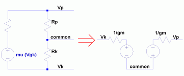
And there are other problems with that model. It is claimed that in simultaneously grounding the (P)late and (K)athode (see the first sim below), the resulting short circuit currents can be used to determine the ground-referenced P and K impedances. Is this so? Well, to measure any impedance, current must flow through it so that the voltage arising across it can be divided by that current. If no current flows, the impedance can’t be measured. Is there any current flowing through ground that is available to either the P or K impedances? Let’s take a look at the following sims and see.
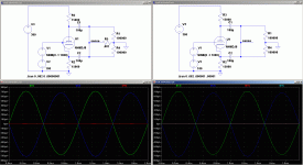
In the first sim, 1 milliohm resistor has been inserted between the ground and the shorted plate and cathode capacitors so that the current into and out of ground can be measured. And although the P and K currents are substantial, equal and opposite, the ground current is exactly zero. In fact, the second sim shows that the ground can be completely disconnected from the shorted plate and cathode with absolutely no change in the currents in the circuit!
There is no ground current. So there is no current available to test the P and K-to-ground impedances. This circuit has no business making any claims about them.
In light of this, how would those of you who say that a balanced Cathodyne must be kept balanced (to measure any of its characteristics) measure its ground-referenced P & K resistances?

And there are other problems with that model. It is claimed that in simultaneously grounding the (P)late and (K)athode (see the first sim below), the resulting short circuit currents can be used to determine the ground-referenced P and K impedances. Is this so? Well, to measure any impedance, current must flow through it so that the voltage arising across it can be divided by that current. If no current flows, the impedance can’t be measured. Is there any current flowing through ground that is available to either the P or K impedances? Let’s take a look at the following sims and see.

In the first sim, 1 milliohm resistor has been inserted between the ground and the shorted plate and cathode capacitors so that the current into and out of ground can be measured. And although the P and K currents are substantial, equal and opposite, the ground current is exactly zero. In fact, the second sim shows that the ground can be completely disconnected from the shorted plate and cathode with absolutely no change in the currents in the circuit!
There is no ground current. So there is no current available to test the P and K-to-ground impedances. This circuit has no business making any claims about them.
In light of this, how would those of you who say that a balanced Cathodyne must be kept balanced (to measure any of its characteristics) measure its ground-referenced P & K resistances?
hey.
by ensuring it was measured in a way to not introduce currents through the ground node?
every way that has been presented to prove unequal plate and cathode impedances has introduced current through the ground node which suggests to me you are not measuring the right thing.
dave
In light of this, how would those of you who say that a balanced Cathodyne must be kept balanced (to measure any of its characteristics) measure its ground-referenced P & K resistances?
by ensuring it was measured in a way to not introduce currents through the ground node?
every way that has been presented to prove unequal plate and cathode impedances has introduced current through the ground node which suggests to me you are not measuring the right thing.
dave
So answer the question – how would you do that?by ensuring it was measured in a way to not introduce currents through the ground node?
Perhaps you would be kind enough to point out a flaw in the following logic:
To measure an impedance, current must flow through the impedor so that the ratio of the voltage across to the current through it can be determined.
P and K-to-ground impedances are connected to ground.
If they are to be measured, current must flow through ground.
No current flows through ground in the previous circuit. Therefore it cannot be used to determine the impedances in question.
P and K-to-ground impedances are connected to ground.
If they are to be measured, current must flow through ground.
No current flows through ground in the previous circuit. Therefore it cannot be used to determine the impedances in question.
“suggests?” Because you are of the opinion that I am wrong, I must be wrong?every way that has been presented to prove unequal plate and cathode impedances has introduced current through the ground node which suggests to me you are not measuring the right thing.
You have to do better than that, Dave. Prove me wrong. Pinpoint where I am wrong. If I really am, you should have no problem doing so. But if you can’t...
It’s instructive to take a look at the differences between how the Long Tailed Pair and the Cathodyne behave when they drive grid current into a pair of matched output tubes.
I’ve biased the LTP and Cdyne triodes identically in the following sims and applied AC signals to their grids such that if the output stages hadn’t drawn grid current, the drivers’ output voltages would have been at the same level.
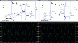
One look at the schematic of the LTP and it’s clear that both halves are identical, right down to and including the impedances they present to the output stage. And a glance at the LTP sim confirms that the voltages and currents and therefore impedances of the halves are identical.
Not so with the Cdyne sim. Here, the cathode-driven currents are tall and narrow, changing rapidly, consistent with the small time constant that results from a low cathode output impedance. Contrast that with the slower, wider, shorter current pulses that come from the higher impedance plate. Similarly, the low impedance cathode can push its way through the coupling-capacitor-grid-current-drawing load of an output tube while maintaining the sinusoidal shape of the Cdyne’s grid voltage. The plate output, however, “hits the wall” and squares off when it encounters the same load from the other (matched) side.
Do we need any further proof of unequal Cdyne drive impedances?
I suspect that die-hards will say that the Cdyne outputs’ impedances are identical until the Cdyne is unbalanced by grid current, first on one side, then on the other of the matched output tubes. I’ll deal with some of the surprisingly weird consequences of such a claim in a later post.
I’ve biased the LTP and Cdyne triodes identically in the following sims and applied AC signals to their grids such that if the output stages hadn’t drawn grid current, the drivers’ output voltages would have been at the same level.

One look at the schematic of the LTP and it’s clear that both halves are identical, right down to and including the impedances they present to the output stage. And a glance at the LTP sim confirms that the voltages and currents and therefore impedances of the halves are identical.
Not so with the Cdyne sim. Here, the cathode-driven currents are tall and narrow, changing rapidly, consistent with the small time constant that results from a low cathode output impedance. Contrast that with the slower, wider, shorter current pulses that come from the higher impedance plate. Similarly, the low impedance cathode can push its way through the coupling-capacitor-grid-current-drawing load of an output tube while maintaining the sinusoidal shape of the Cdyne’s grid voltage. The plate output, however, “hits the wall” and squares off when it encounters the same load from the other (matched) side.
Do we need any further proof of unequal Cdyne drive impedances?
I suspect that die-hards will say that the Cdyne outputs’ impedances are identical until the Cdyne is unbalanced by grid current, first on one side, then on the other of the matched output tubes. I’ll deal with some of the surprisingly weird consequences of such a claim in a later post.
It’s instructive to take a look at the differences between how the Long Tailed Pair and the Cathodyne behave when they drive grid current into a pair of matched output tubes.
That's a totally unfair boundary condition for the concertina to mimic class 2 grid current flow, the tube has deal with the o/p tube 1/gm to control the substantial grid current at low Z.
Morgan Jones Valve amps 3rd ed p.386.
All the mathematical arguments pertaining to the concertina as per Albert Preismann's article dated 1960 use class A condition. Lock stop and barrel and one need to know no more.
From the practicals; the concertina has half the voltage swing compared to others, but the distortion from a optimised design is also way lower than the LTP configuration sim to the configuration in a Mullard 20W, where the design quotes 1.8% thd with 20+20V rms swing into a high impedance load with a drastic HF rolloff.
richy
Unfair? Life is unfair! The Concertina is not exempt. When called upon to overdrive output tubes, this is what it does.
Are you saying that we can't talk about something unless Preismann has dealt with it? That it is impossible for the Concertina to ever face conditions that Preismann has not discussed? Wow!
You have noted, of course, Preismann's equations (1) and (2) stating right from the very start of his article that the P and K impedances are unequal?
Please don't interpret anything of what I said in the last post to favor the LTP over the Cdyne. That was not the subject of the post. It was only to point out the balanced drive impedance of the LTP and the unbalanced drive impedance (with respect to ground) of the Cdyne.
Hi CPaul !
Question :
What well happen if you use Two triode section of 6bm8 tube connected in parallel for Cdyne splitter/driver unit to drive that two 6as7g grids ?
Since your LTP splitter/driver unit use Two separate 6bm8 triode section units , but your Cdyne unit use only One triode unit !
Just think that for correct & fair sims results you have to use the same number of 6bm8 triode section for both different type of splitter /driver configuration .
Best Regards !
Once again, the point of the post was not to say that the LTP is a better choice for a splitter than the Cdyne.
The point was to show that the Cdyne has unequal plate and cathode to ground impedances and to contrast it with a phase splitter that has equal ones.
That's all.
The point was to show that the Cdyne has unequal plate and cathode to ground impedances and to contrast it with a phase splitter that has equal ones.
That's all.
Once again, the point of the post was not to say that the LTP is a better choice for a splitter than the Cdyne.
The point was to show that the Cdyne has unequal plate and cathode to ground impedances and to contrast it with a phase splitter that has equal ones.
That's all.
In any case my point was Not that LTP is better choice for splitter / driver unit than Cdyne , (or opposite ) ,
Or that Cdyne splitter have equal / unequal anode or cathode to ground impedance , but was only the question of practical equal number of used triodes section for both types of different phase splitter/driver unit configuration , and the final sims results under I think this equal condition .
Any way Thanks !
Last edited:
Hi Banat, I understand your point. I didn't sim with two Cdynes in parallel because I didn't know why anyone would want to do that - they'd need the other triode for gain.
I modified the Cdyne sim for two triodes in parallel and kept their biases the same as those of the LTP's by changing the two Cdyne P and K loads from 20K to 10K. The result was very little change.
If there's any interest, I can post the .asc simulation files.
I modified the Cdyne sim for two triodes in parallel and kept their biases the same as those of the LTP's by changing the two Cdyne P and K loads from 20K to 10K. The result was very little change.
If there's any interest, I can post the .asc simulation files.
I have not been following this thread for few months and not been reading latest posts thoroughly, but is it really so that here still some do not realize that the output impedances of the cathodyne are far different?
Yes, they "look" same with identical loads, but this is just theory.
In practise two identical loads do not exist.
Yes, they "look" same with identical loads, but this is just theory.
In practise two identical loads do not exist.
Yes, artosalo. I believe you can count SY and DaveSlagle among them. There may be others.
I'm doing my best.
I'm doing my best.
Hi Banat, I understand your point. I didn't sim with two Cdynes in parallel because I didn't know why anyone would want to do that - they'd need the other triode for gain.
I modified the Cdyne sim for two triodes in parallel and kept their biases the same as those of the LTP's by changing the two Cdyne P and K loads from 20K to 10K. The result was very little change.
If there's any interest, I can post the .asc simulation files.
CPaul thanks for your efforts !
I was expected to be something just as you say :` The results was very little change` .
My personal conclusion is that even if we connect in parallel Two same triode section for Cdyne to achieve the same operational condition as is for LTP , final practical results well be the almost the same as for Cdyne configured from standard single triode section !
Thanks again !
Last edited:
- Home
- Amplifiers
- Tubes / Valves
- phase splitter issue