Zman...the existing baffle hole will get enlarged. I'm talking about creating a rebate in the supra baffle. I may just create a CNC design for the supra baffle.
faithintruth,
I use a Jasper jig to make the driver cut-outs. A DIY jig (if you can make one) should also work fine.
First make a hole of required diameter and depth for the driver frame+bezel. For example for the Alpair 10P, maybe 166mm diameter (assuming bezel ring will also be used), 11mm deep. Then cut a circle of required diameter through the full depth of the material (for Alp 10P anywhere from 136-138mm should work).
If you have access to a CNC then it becomes even easier. 🙂
Has any one used a rabbeting bit (bearing on the bottom) to create a rebate from an existing hole? This should work like a charm, no?
Maybe, if the through hole is precise - I like to allow approx 1mm oversize on both the through hole (140 mm for the A10) and outer rebate for an easy fit . Without the extra bezel, the outer diameter of flange is 160mm, and with the bezel, it's 164mm
Based on a 140mm through hole, using something like the set below, the 7/16" rabbet will be a good 2mm wider overall than needed if not using the wider bezel, and with the bezel, the 1/2" rabbet would leave approx 1.5mm gap
https://www.amazon.ca/Yonico-14705q...1466360386&sr=1-2&keywords=bearing+router+bit
Of course, I'm one of those guys fortunate enough to still have access to a CNC router, and programs for all the MA and Fostex drivers are saved in the machine console.
Then there's the issue of chamfering the backside and those very acute angled cuts in the Supra-Baffle panels. I use a very large 45dg bit on router for the former, and a tenoning jig with the save blade set to the calculated angle for the latter. Even then, with thick enough material, there might not be enough depth/height of cut, and finishing by hand with rasp or coarse sand paper glued to a dowel might be required for the former, and Japanese style draw saw* for the latter.
*next to a decent and sharp 2" wide chisel, one of the best small hand tool investments under $100 I've ever made.
Ok so...
A 12 mm rabbet bit will work for the rebate. Thanks Chris for the lengthy explanation. Part of it I didn't understand but most of it yes.
I drew up the plan with a 35mm thickness. I think it will protrude but not as much as many supra baffles. With this thickness, I get two 45° angles on the vertical sides. The very shallow (acute) angle above and below the driver is about 17°. I think I'll cut it close on a band saw and plane it down to the line.
Really what I should do on the next build is cnc the whole front baffle with steep angles that fall away from the driver in all directions with the baffle tapering below the driver all the way to the floor. (I've been reviewing the nice baffles on Focus Audio speakers amongst others.)
Should have pics this week.
Attachments
Last edited:
If you have a CNC that can cleanly machine those very acute angles for the longer tapers, that's great.
I think an issue you might encounter is the depth/height of cut required for the 17dg bevel at top/bottom of your sketch. By my math, that hypotenuse works out to approx 124mm, while the 45dg on the longer sides is approx 50mm.
The latter shouldn't be too hard to cut on table saw (I'd do those last), but it could be a bugger to cut the 17dg bevels on the 241mm wide pieces on a band saw. I'd think again about using or fabricating a tenoning jig that can securely clamp the pieces vertically and set the table saw blade at the required angle. It might take a few passes to reach the maximum height of cut and would likely require a hand saw to finish off - and there could be some minor burning - but I think you'd get higher precision on all 4 cuts.
Then of course, there's the matter of the deep chamfer required on the rear side of driver cut-out. That's a lot of material to chew through, particularly by hand - the gray shaded area on attached sketch.
Attachments
Hi Chris
Thanks for that sketch. Mine is below. I got 50 mm and 120mm exactly for the two different bevels. Tricky bugger this thing. I was thinking a round-over bit would be enough for the back side. Your sketch shows alot of material to be removed....leaving only a little meat for the screws ( the reason I decided against a 1" supra baffle)
I may have to make it from 4 or 5 pieces. I don't have my own cnc but I know a place to ask.
Keep you posted here
Attachments
Hi Chris
Thanks for that sketch. Mine is below. I got 50 mm and 120mm exactly for the two different bevels. Tricky bugger this thing. I was thinking a round-over bit would be enough for the back side. Your sketch shows alot of material to be removed....leaving only a little meat for the screws ( the reason I decided against a 1" supra baffle)
I may have to make it from 4 or 5 pieces. I don't have my own cnc but I know a place to ask.
Keep you posted here
Using the Alpair's supplied screws, and with carefully piloted and pre-tapped holes, I honestly don't think a lot of thickness of core material is actually required. I realize that my hasty sketch did not reveal that the chamfer is not continuous, but scalloped to leave full thicknes "pads" at each of the screw locations. That does of course make for a more time consuming process with thicker material.
Their outstanding performance notwithstanding, these are after all relatively light weight, low moving mass full range drivers, not 18" monster car audio subs.
For the Planet10 FH3 kit Supra baffle option 18mm BB is used, and for A7.3 the combination of the slightly shallower driver rebate and rear side chamfer leaves less than approximately 1/2 of the core thickness, which I think is still sufficient.
Of course I've used exclusively BB grade plywood in my builds for well over a decade, and not the least of its advantages over MDF or particle board is superior screw holding capacity - particularly with the narrow margins involved with this class of drivers.
A round-over bit will not remove as much material as a similarly sized 45dg chamfer bit.
Last edited:
yup, Zia's photo shows it exactly - it does take close monitoring to see what's going on inside the router base plate, so definitely wear eye protection.
The thickness of the bezel is such that flush mounting makes a significant difference.
dave
okay thanks.
I'd allow at least 1mm over measured outer diameter of flange to allow for a looser than a interference fit when rebating any of the Alpair drivers - the flanges are thick enough that a "perfect" fit can have a lot of friction, and aligning with mounting screw holes, much less removing the driver if necessary can be a bit tricky.
I'd allow at least 1mm over measured outer diameter of flange to allow for a looser than a interference fit when rebating any of the Alpair drivers - the flanges are thick enough that a "perfect" fit can have a lot of friction, and aligning with mounting screw holes, much less removing the driver if necessary can be a bit tricky.
That's good to know, thanks. I was hoping I could surface mount it instead of flush mount, not sure if anyone has different measurements on flush and surface mount for Alpair 10.3. I checked out Zaph audio about surface and flush mounted but his test is on a woofer 1/4 inch flange I believe (not sure how that would apply to full range) and not really any difference between surface and flush mounted for woofer. Tweeters have a big difference if surface mounted as per zaph audio tests. Alpair 10.3 won't be in a pencil but on the Denovo pre-cut tower from parts express, ported.
Denovo pre-cut tower from parts express
The aspect ratio of that box will make it an ML-TL (far too big for a well-aligned BR anyway), you should model it to make sure it will work. If you can't do that look for a ½ ft^3 box which would be appropriate size for an A10.3 reflex.
Also the braces run the wrong way for an ML-TL. You will need to either redo them (hard), or put more air into the exitisting ones (easier, but will affect the flow of the QW slighly).
They are cheap thou.
dave
Or you could make a solid brace to divide the volume in 2. put the speaker in the top cavity and put sand or such in the bottom.
dave
dave
The aspect ratio of that box will make it an ML-TL (far too big for a well-aligned BR anyway), you should model it to make sure it will work. If you can't do that look for a ½ ft^3 box which would be appropriate size for an A10.3 reflex.
Also the braces run the wrong way for an ML-TL. You will need to either redo them (hard), or put more air into the exitisting ones (easier, but will affect the flow of the QW slighly).
They are cheap thou.
dave
Yes thanks, i have modeled it in bassbox pro 6 using the denovo dimensions. have put it in leonard audio as well for port placement. wont be using bracing as it is a small driver. graphs look good.
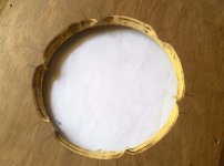
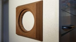
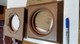
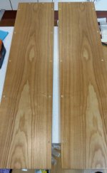
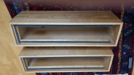
After a long break I am making progress with the pencil suprabaffles. They are the width of the box, square. Truncated square-based pyramid. The chamfor is approx 39°. The rebate is a little deep so I routered out a gentle horn. The underside is well scalloped for allowing ventilation. I will post more pictures in the next few days.
Attachments
- Home
- Loudspeakers
- Full Range
- Pensils for Alpair 10.3 & Alpair 10p