Nice!
Can you say something about sound card used?
Can you post the schematic of voltage divider at sound card input?
I want to know how the inp. & out.Gnd was connected.
Hi thimios.
The sound card is my PC's onboard realtek HD. Nothing "audiophile", input SR 96KHz(this is why the FR is down a few dB near 40KHz) output SR 192KHz.
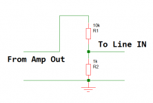
The attached pic shows the schema of the resistor divider I use. The ground is common. The 1KHz input signal is from a WAVE file played in my cellphone and not from PC as doing so creates the dreaded ground loop and I can see motorboats all around. 😀
edit: forgot pic. here it is now!
Attachments
Last edited:
A separate oscillator(in your case the wav file)is a solution for ground loops.
Is the source distortion low enough (lower the amplifier distortion) to be able to check?
How you test the frequency response then?
Is the source distortion low enough (lower the amplifier distortion) to be able to check?
How you test the frequency response then?
A separate oscillator(in your case the wav file)is a solution for ground loops.
Is the source distortion low enough (lower the amplifier distortion) to be able to check?
How you test the frequency response then?
My signal source reads 0.01% at best, which is better than one I built using opamp. Reading more to build a very clean oscillator.
For freq-response I use pink noise from another 1 hour long wav file. It was recorded from the spectrum analyzer's output, in software.
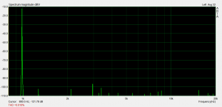
Also, the frequency is around 980Hz and not exactly 1000Hz, though that difference doesn't matter much in measurements.
Hi Friends.
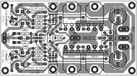
Here goes the PDFs for the new V2 layout.
Cheers and happy building!!!
🙂
shaan
Here goes the PDFs for the new V2 layout.
Cheers and happy building!!!
🙂
shaan
Attachments
Hi Friends.
Here goes the PDFs for the new V2 layout.
Cheers and happy building!!!
🙂
shaan
Sir,
What is the total power in RMS of this V2? Also, how am I going to set-up the bias?
Regards,
Vinski80
Excellent pcb.Hi Friends.
Here goes the PDFs for the new V2 layout.
Cheers and happy building!!!
🙂
shaan
Shaan, you have done a very good job.
Congratulations.
Thimios.
Sir,
What is the total power in RMS of this V2? Also, how am I going to set-up the bias?
Regards,
Vinski80
Hi vinski.
It's ~160W into 8ohms with +/-56V.
VAS bias is set by the 27K resistors near the input section. With typical VAS hFE of 150-200 the default resistor should be adequate for about 5-10mA of VAS bias. If hFE is higher then use 33K. Output bias is auto-set by the 1N4148 diode to about 80mA total. Use the 2k2 trimmers for trimming the output offset voltage, start with the slider at maximum resistance(upper trimmer full-up and lower trimmer full-down).
Saan, are you using matched fets in this V2?
No. Only matched input and VAS.
Hi vinski.
It's ~160W into 8ohms with +/-56V.
VAS bias is set by the 27K resistors near the input section. With typical VAS hFE of 150-200 the default resistor should be adequate for about 5-10mA of VAS bias. If hFE is higher then use 33K. Output bias is auto-set by the 1N4148 diode to about 80mA total. Use the 2k2 trimmers for trimming the output offset voltage, start with the slider at maximum resistance(upper trimmer full-up and lower trimmer full-down).
Thank you so much sir..
Regards,
Vinski803
Hi QQ!
Looking great!
You can use a 25V-0-25V transformer for more power and lower distortion. Might need to readjust the trimmers for correcting VAS bias and output offset.
You're officially the first among my fellows here to have built V1.1. So feel free to mention your building and listening experience with PeeCeeBee in detail if possible.
Have fun!
shaan
Hi QQ!
Looking great!
You can use a 25V-0-25V transformer for more power and lower distortion. Might need to readjust the trimmers for correcting VAS bias and output offset.
You're officially the first among my fellows here to have built V1.1. So feel free to mention your building and listening experience with PeeCeeBee in detail if possible.
Have fun!
shaan
Hi Shaan, i have to find another transformer tu test again with required voltage. Than i'll give my listening experince.
Regards

Hello QQ.
Which model are the Elna capacitors?
Thanks.
Hi Shaan,
It's Elna RJ3 2200uF/16v
Hi shaan!
Congrats for your excellent design again, but let me go back to FETs bias. You wrote that V2 hasn't audible difference compared to the original PeeCeeBee wich has much higher, (say 160mA) quiescent current setting. That's strange. It is easy to see that there's no sonical benefit to increase the bias above 200mA, but 30-40 mA seems to be too low.
Someone says there's no such thing as optimum bias for LATFETS, but only for bipolars. Nevertheless choosing such low bias you can easely reach the positive tempco area of FEts, which seems to be suboptimal. Not to mention the increased high-order harmonic distortion. If I remember correctly G. Randy Slone is the only one who suggests such low quiescent current for LATFETs (without any explanation). Everyone else suggests much higher current. I'm not a technical guy, so any further explanation is welcome about your decision.
Thank You
egra
Hi egra.
The choice of lower bias in V2 was for limiting idle dissipation. I didn't measure or hear any increase of odd-order distortion over V1.1 which has about 180mA of FET bias but uses somewhat "inferior" VAS transistors with somewhat lower hFE. Maybe the MJEs are really a better option for VAS stage than the BDs. Now, if the distortion is okay with 1/4 the bias and the amp sounds okay through the same speakers, then I think 30mA is okay as well.
Ideally the feedback alone should have ultimate control over the sonics, not the devices. And looking at the plots, I think the feedback in V2 is doing well. I could increase the gain to say 40 (because the V2 has a higher PS voltage and with the default gain will probably need a preamp for max output swing) but that would naturally increase odd order distortions much higher than with 10mA FET bias because there is less available feedback factor than with the default gain.
My experiments with the PeeCeeBee haven't stopped btw. So correct me if I'm wrong, much appreciated.
Thanks.
shaan
Thank You shaan! These are very good news! I like the original PeeCeeBee very much, thus more power with less heat should be really impressive.
"Ideally the feedback alone should have ultimate control over the sonics, not the devices." This is a very interesting question. It is certainly true however I'm very curious how these capacitors sound in V2:
http://www.ebay.ca/itm/2-pcs-Sanyo-OS-CON-SA-2200uF-6-3V-Organic-semiconductive-Capacitors-ESR-15m-/262316786794?hash=item3d134c846a:g:RJ8AAOSw~bFWJkSQ
These have very good reviews, and they are much cheaper (and smaller) than the "regular" Nichicon FGs. Using smds in all possible position you can easily build a 160W power amp with "shortest signal path ever".
All in all it seems to be a new "Must-Build' PeeCeeBee was born. 🙂
Regards
egra
Last edited:
- Home
- Amplifiers
- Solid State
- PeeCeeBee