My own failure,sorry Andrej,sorry Gabor.
edit- The circuit design credit goes to Gabor and Andrej. I just shared my board layout of it.

Congratulation to all of you!
Best Regards
Thimios.

No, all this test is on a dummy load.
I will test it on a real speaker if request.
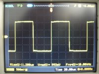
Isn't safe leaving this uncompensated without test this with a scope!
If you haven't a scope pay attention ,put your finger on zobel resistor this must be cold.
Out transistors must be cold also ,when amplifier isn't playing.
I just wondered would it be more likely to oscillate with real(inductive) load.
If I decide to remove them I'll test if for oscillations, if I remember well there is relatively simple and easy to diy circuit able to detect them.
I just wondered would it be more likely to oscillate with real(inductive) load.
If I decide to remove them I'll test if for oscillations, if I remember well there is relatively simple and easy to diy circuit able to detect them.
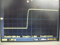
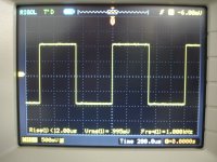
It does not oscillate with squarewave output in capacitive load, as thimios' plots indicate. I am using the same boards with same components and no compensation in my main system and sub amplifier for over a year and half and so far they have shown no ill behavior. If you use Zobel at output then this thing can drive any loudspeaker effortlessly. Of course you must not omit 100pF at input, otherwise it will try to amplify 500KHz RF signal too and zobel resistor will catch fire and you will hear sounds from random radio stations. 😀
All the best for your experiments.
Last edited:
It does not oscillate with squarewave output in capacitive load, as thimios' plots indicate. I am using the same boards with same components and no compensation in my main system and sub amplifier for over a year and half and so far they have shown no ill behavior. If you use Zobel at output then this thing can drive any loudspeaker effortlessly. Of course you must not omit 100pF at input, otherwise it will try to amplify 500KHz RF signal too and you will hear sounds from random radio stations. 😀
All the best for your experiments.
I'm using Jason's TO3 layout with no zobel, 100pf at input, 22pf comp caps. Had no any issues so far. I like the sound.
I guess it is not recommended to remove comp caps with no zobel in place?
If the board is stable with 100pF at input and no compensation capacitor then a zobel at the output will be enough to ensure stable operation into inductive loads. This config prevents external HF interference from entering the feedback loop through either input or output and that, coupled with zero additional internal compensation means a stable amp with high slew rate.
I'm using Jason's TO3 layout with no zobel, 100pf at input, 22pf comp caps. Had no any issues so far. I like the sound.
I guess it is not recommended to remove comp caps with no zobel in place?
I guess Jason can give you a better answer.
However, if you like the sonics then IMO keeping it intact is the best way to go, coz its the sound that matters most.

Last edited:
I will test it on a real speaker if request.
Thimios, did you play music with PeeCeeBee? How does it sound? Good/Bad?
Hi Shaan this playing very good !Thimios, did you play music with PeeCeeBee? How does it sound? Good/Bad?
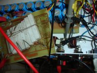
Now again on test procedure.
First testing on a real 3way speaker.
+/-32V
43.000uf/rail
offset=0mv(2M2//16K)
I rail=120mA
Rspeaker=8R
Attachments
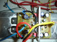
Peeceebee
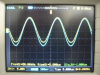
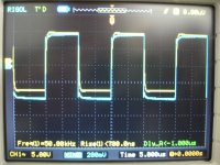
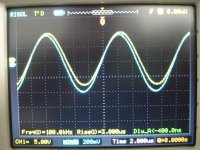
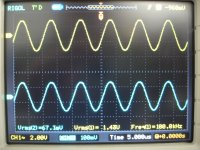
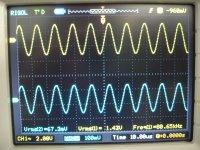
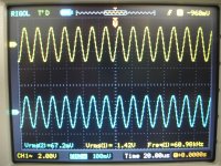
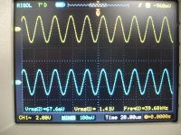
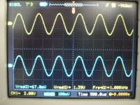
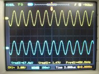
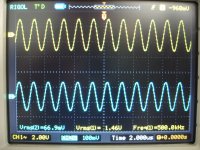
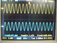
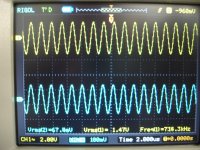
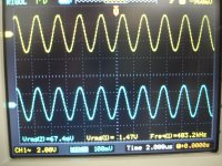
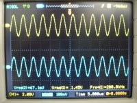
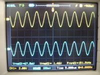
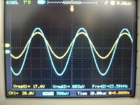
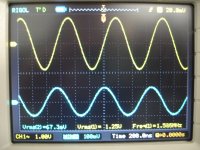
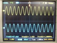
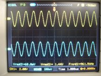
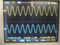
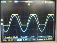
A bandwidth test on a dummy load=6R
Yellow wave is out signal
blue wave is input signal.
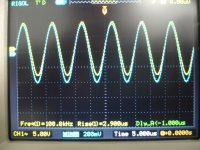
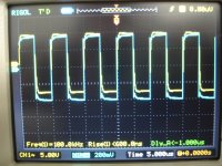
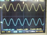
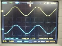
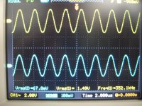
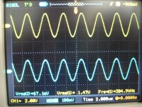
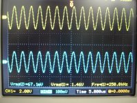
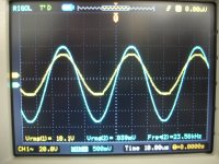
A bandwidth test on a dummy load=6R
Yellow wave is out signal
blue wave is input signal.
Attachments
-
 DSC08630.JPG544 KB · Views: 118
 -
 DSC08629.JPG571.1 KB · Views: 118
 -
 DSC08628.JPG587.8 KB · Views: 108
 -
 DSC08627.JPG597.6 KB · Views: 104
 -
 DSC08626.JPG548.5 KB · Views: 109
 -
 DSC08625.JPG598.3 KB · Views: 106
 -
 DSC08624.JPG554.4 KB · Views: 106
 -
 DSC08623.JPG575.8 KB · Views: 122
 -
 DSC08622.JPG543.6 KB · Views: 150
 -
 DSC08619.JPG617.8 KB · Views: 231
The rest
Attachments
-
 DSC08638.JPG549.1 KB · Views: 86
 -
 DSC08639.JPG574.6 KB · Views: 86
 -
 DSC08640.JPG602.2 KB · Views: 88
 -
 DSC08641.JPG574.9 KB · Views: 97
 -
 DSC08637.JPG553.1 KB · Views: 88
 -
 DSC08635.JPG605.9 KB · Views: 514
 -
 DSC08634.JPG610.1 KB · Views: 541
 -
 DSC08633.JPG572.6 KB · Views: 590
 -
 DSC08632.JPG551.6 KB · Views: 642
 -
 DSC08631.JPG612 KB · Views: 703
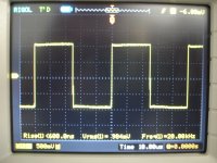
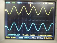
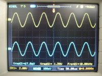
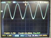
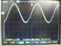
photo maximum unclipping level, last photo a step after clipping level.
Attachments
-
 DSC08649.JPG594.3 KB · Views: 87
 -
 DSC08650.JPG617.7 KB · Views: 97
 -
 DSC08651.JPG578.9 KB · Views: 98
 -
 DSC08652.JPG592.8 KB · Views: 113
 -
 DSC08648.JPG603.8 KB · Views: 85
 -
 DSC08646.JPG579.7 KB · Views: 80
 -
 DSC08645.JPG592 KB · Views: 92
 -
 DSC08644.JPG569.2 KB · Views: 92
 -
 DSC08643.JPG557.4 KB · Views: 92
 -
 DSC08642.JPG612.3 KB · Views: 95
Last edited:
Shaan, not necessary the best idea.Seems my choice of 2K2/100R over 1K/47R is justified. No additional compensation necessary to successfully build a stable and working PeeCeeBee.
It is traditional to use the feedback impedance to set the bandwidth of a Current feedback OPA. (In conjunction with the input transistors emiters parasitic capacitances).
But, remember, this capacitance is *not* linear. Means this has an impact on HD.
Hi Esperado.
Yes, not necessarily the best thing to do, as we always used to think(myself included).
However, as you can see the amp is stable without it(comp cap, that might be a must if 1k 47r is used) and the intrinsic capacitance being a few pF is not a concern at the audible frequency range.
My choice of 2K2/100R is based on the idea of limiting the GBW before HF phase lag becomes a concern. So far this config seems to serve its purpose well in this amp, i.e. a stable amplifier that can drive reactive loads well.
'High quality', 'high definition', etc. are more the effects of the bandwidth, sensitivity and distortion performance of the speaker drivers and that can vary from system to system.
Me and a few others here has found out the comp cap unnecessary to build the amp. This indicates that this amp can be run with this config by othes too.
Of course one can't be 100% sure until detailed tests are done, and I am greatful to Thimios exactly for doing this. Except for the -ve hard clip plot(which has more to do with a saturated device than an oscilating amp), I think those readings suggest this amp can run better without additional capacitor compensation at VAS.
Last edited:
Shaan, not necessary the best idea.
Surely there is always trade-off. And Shaan has his own way to weight things.
It is traditional to use the feedback impedance to set the bandwidth of a Current feedback OPA.
Such that the bandwidth is soooo wide, may be more than necessary, who knows. And yes, Shaan's decision limits the bandwidth.
But, remember, this capacitance is *not* linear. Means this has an impact on HD.
Correct again, but I believe Shaan has already know that. I think ears should be the arbiter here. It seems that NFB fixes most of the problem with this capacitance.
Shaan, not necessary the best idea.
It is traditional to use the feedback impedance to set the bandwidth of a Current feedback OPA. (In conjunction with the input transistors emiters parasitic capacitances).
But, remember, this capacitance is *not* linear. Means this has an impact on HD.
Is there a way to work around it other than decreasing the FB resistance and adding Compensation to the next stage?
I don't see ;-)Is there a way to work around it other than decreasing the FB resistance and adding Compensation to the next stage?
I use always the same method, on my side.
Setting a comp cap between the feedback source and base of the VAS in order to have a flat bandwidth as wide as possible (no peak at HF), then an input filter to kill any overshoot on square waves little signals.
Post a shematic of this Peeceebee additing this compensation capacitor.🙂I don't see ;-)
I use always the same method, on my side.
Setting a comp cap between the feedback source and base of the VAS in order to have a flat bandwidth as wide as possible (no peak at HF), then an input filter to kill any overshoot on square waves little signals.
Setting a comp cap between the feedback source and base of the VAS in order to have a flat bandwidth as wide as possible (no peak at HF),
Do you see a peak at H.F in my previous test?I want to know if this occurs.😕
Last edited:
A lot of people use a lot of types of compensation for a lot of amplifiers in lots of different way. I use none, and respectfully disagree that my system sounds less "HD" than anybody else in this forum.
For the purpose of keeping this thread's topic intact, please post build stuff only. If a schematic uses any compensation except Miller type then please open a new thread and bring the discussion there. I will be happy to join and learn new things.
For the purpose of keeping this thread's topic intact, please post build stuff only. If a schematic uses any compensation except Miller type then please open a new thread and bring the discussion there. I will be happy to join and learn new things.
- Home
- Amplifiers
- Solid State
- PeeCeeBee