 I like the common heatsink! I started working on that a bit earlier, but ran out of time.
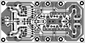
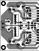
New plan of double FET PeeCeeBee with VAS + OP Stage on main heatsink.
I like Your plan anyway.
New plan of double FET PeeCeeBee with VAS + OP Stage on main heatsink.
That's it...very good.
Marc
Thanks guys.
Please tell me if there is any modifications that should be done, coz the pdfs will be released soon.
shaan
Please tell me if there is any modifications that should be done, coz the pdfs will be released soon.
shaan
Theres enuff space for zobel not to stand. Looks bad that way. Coupling cap can also axial type. Is this for the same schematic?
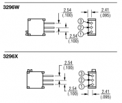
Shaan, please add optional pattern for multiturn bourns trimmer (like in PMI's peeceebee layout)
Theres enuff space for zobel not to stand. Looks bad that way. Coupling cap can also axial type. Is this for the same schematic?
Hi Jay.
Okay I'll try to place the resistor laterally.
Extra space for axial type input cap probably won't be added this time, but later, sure.
Thanks for the suggestions.
Shaan, please add optional pattern for multiturn bourns trimmer (like in PMI's peeceebee layout)
I'll try. Post a footprint of the pins, what is pin spacing?
Really??? I like to have one pcb for all the vssa variants, bjt or fet, with parallelled mkp. Not every trace should be short. Even with single side pcb, components can be arranged like dual side.I think it's best to make two versions, one for cheap single turn and another for multiturn. No space for adding both in one.
Nice looking layout, Shaan, I like it. (I will try to take a close look tomorrow, it was a busy weekend.)
What power supply voltage range are you planning to specify for this circuit?
What power supply voltage range are you planning to specify for this circuit?
Assuming we are, this is how the mt-POT version's front-side will be.
I think it's best to make two versions, one for cheap single turn and another for multiturn. No space for adding both in one.
Hi Shaan,
Can you make it vertical version as it will be hard to adjust on its side.
Thanks
The pinout/footprint is the same, for the top-adjust version.Hi Shaan,
Can you make it vertical version...
In other words, the pin spacing, and the wiper-to-center configuration is identical, whether you have the side-adjust, or the top-adjust version.
There are two common footprints, a triangle, and a straight line. The price is usually dependent on the number of turns, and the resistance, not the footprint.
Ok Thanks for the info but can we adjust it to accommodate both the straight & triangle footprint so we can use whatever footprint is available in our drawer.
Really??? I like to have one pcb for all the vssa variants, bjt or fet...
hi Jay.
We already got six different PCB designs with different looking components based on the most basic version and awaiting the seventh, only FET o/p stage.
...with parallelled mkp...
Of course. But, Not in this thread and No discussion on it any more. 😉
I'm trying to make sure that the dual FET board is free of layout errors as I might not be the first to etch it, and I want the first guy that does that to have a working, stable amplifier on his bench.
I'm grateful to have so many constructive comments that only helps broaden my knowledge and experience. I'm happy to have the chance to share the layout with everyone here, and thankful to the big bros who shared their own works (I'm only 28 🙂 ).
shaan
Nice looking layout, Shaan, I like it. (I will try to take a close look tomorrow, it was a busy weekend.)
What power supply voltage range are you planning to specify for this circuit?
Thanks.
The PS voltage can be anything within limit of the devices, the decouple caps' voltage will follow that too. I'm going to use it with +/-42V with high voltage input and VAS transistors.
Hi Shaan,
Can you make it vertical version as it will be hard to adjust on its side.
Thanks
Hi presbel.

As PMI says, the pinout is the same!
...can we adjust it to accommodate both the straight & triangle footprint so we can use whatever footprint is available in our drawer.
Yes of course.
 😀
😀- Home
- Amplifiers
- Solid State
- PeeCeeBee