Shaan,
Not looking to pollute the thread but I have a bunch of 2SK135/2SJ50 Hitachi devices and am working on a layout to accommodate those. When it is complete may I post it for review here? It will be your schematic (may have some minor value alterations to suit what I have on hand). Once it is worked out I will be making at least a pair to compare with LC's official VSSA when those kits become available.
Not looking to pollute the thread but I have a bunch of 2SK135/2SJ50 Hitachi devices and am working on a layout to accommodate those. When it is complete may I post it for review here? It will be your schematic (may have some minor value alterations to suit what I have on hand). Once it is worked out I will be making at least a pair to compare with LC's official VSSA when those kits become available.
Hi jkuetemann.
No problem as long as the peeceebee philosophy is maintained, i.e. 1)all through hole parts, 2)single layer layout and 3)no CCS.
shaan
No problem as long as the peeceebee philosophy is maintained, i.e. 1)all through hole parts, 2)single layer layout and 3)no CCS.
shaan
No problem as that was the intent anyway. I just wanted to make use of what I have at my immediate disposal.


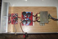
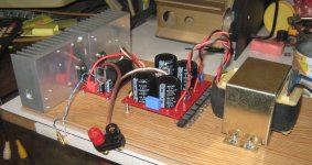
It works!
For now just for a few minutes. Mosfets at cap multiplier get hot, so I must put them on heatsink. I planned when some day I make enclosure, to fix mosfets and rectifying diodes to bottom plate.
It's too early to speak about sound, all I can say is this is poor man's amp, but the sound is very rich.
Last edited:
I just wanted to make use of what I have at my immediate disposal.
Surprise us! 🙂
View attachment 338746
View attachment 338747
It works!
For now just for a few minutes. Mosfets at cap multiplier get hot, so I must put them on heatsink. I planned when some day I make enclosure, to fix mosfets and rectifying diodes to bottom plate.
It's too early to speak about sound, all I can say is this is poor man's amp, but the sound is very rich.
Congrats dobrivoje!

Just a thought... with the cap multiplier it's no longer a poor man's amp, is it? Did you try a simple dual supply with only bridge and caps?
...Did you try a simple dual supply with only bridge and caps?
I already explained that I used cap multiplier to lower supply voltage to less than 35V. Cap multiplier is simple - one mosfet, one electrolytic capacitor, one diode and two resistors. Ripple is much smaller and you don't hear thump at start up.
Anyway, I'll try without cap multiplier and report soon.
oopz! Sorry I probably missed the post. 😱
Looking forward to hearing more of peeceebee experiment from you.

Last edited:
Sounds like a Star Wars character. A partial rendition for my cache of 2SK135 / 2SJ50 outputs, still a work in progress...
Very nice

Sk135/sj50 cost 10 times than 1 pair renesas 1058/162 in my country 😱
Ah. This looks pretty cool! Thanks for sharing kuetemann. Awaiting the real thing. You've got some xotic and xpensive FETs for it, are they laterals? Those goldies just don't exist where I live. Hm, a peeceebee for TO3, much appreciated.
All the best!
shaan
All the best!
shaan
jkuetemann -shaan
Very good job
I look forward to the final stage of board with ΤΟ3
I hope to share this board ,
I have a few pairs ECXICON TO3....
Regards Nikos
Very good job
I look forward to the final stage of board with ΤΟ3
I hope to share this board ,
I have a few pairs ECXICON TO3....
Regards Nikos
Sounds like a Star Wars character. A partial rendition for my cache of 2SK135 / 2SJ50 outputs, still a work in progress...
Nice layout kuetemann.
However, the 1000uF electros at the feedback node seem to be missing; the 100R doesn't look like connected to ground in any way(AC or DC).
Nice layout kuetemann.
However, the 1000uF electros at the feedback node seem to be missing; the 100R doesn't look like connected to ground in any way(AC or DC).
I did mention it was partial and a work in progress 😉, there are a few components not yet placed on the board and missing connections. I just wanted to give a snapshot, more to follow. And yes, the devices are some of the original Hitachi laterals.
I've replaced trimmer with fixed resistor as close as I could.
Supply +-40vdc (32vac)
Dco 9-10mv
Vas bias ~10mA
Input bias ~2.3mA
And load with 4ohm (parallel 2 bookshelf), I can't believe my ears.. the sound was incredible. Crispy trebles, punchy bass, open mid... and relaxing sound.
Best sounding amp I've ever assembled so far.
Supply +-40vdc (32vac)
Dco 9-10mv
Vas bias ~10mA
Input bias ~2.3mA
And load with 4ohm (parallel 2 bookshelf), I can't believe my ears.. the sound was incredible. Crispy trebles, punchy bass, open mid... and relaxing sound.
Best sounding amp I've ever assembled so far.
Thanks Naf, congratulation.
I must build this one 🙂
Please, can you tell me all transistors you use? Are they all matched?
cause I don't have pairs C grade BC's(only BC550C)
to Shaan it is OK if I post my PeeCeeBee design here?
(I want to made my own PCB layout)
Regards
I must build this one 🙂
Please, can you tell me all transistors you use? Are they all matched?
cause I don't have pairs C grade BC's(only BC550C)
to Shaan it is OK if I post my PeeCeeBee design here?
(I want to made my own PCB layout)
Regards
Thanks Naf, congratulation.
I must build this one 🙂
Please, can you tell me all transistors you use? Are they all matched?
cause I don't have pairs C grade BC's(only BC550C)
to Shaan it is OK if I post my PeeCeeBee design here?
(I want to made my own PCB layout)
Regards
Hi JOHN,
I use bd139/140 for vas, bc550/560c for input pair and
I only matched input pair transistor as close as I have in my draw.
I've made two kind of layout. one with bc550/560 and the other sa970/sc2240
- Home
- Amplifiers
- Solid State
- PeeCeeBee
