Now i m listening to the one working amp with other dac (secure one)... and monitoring the temperature.
The dac that i used yesterday i think i has a problem that triggered some instability. I don t have preamp yet so i connected the dac direct to amp. Today i measured the output of the dac not connect to amp and without music playing and have almost a negative 1 v dc. When playing music has no dc. Since vh4 don t have input cap and the insecure dac don t have output cap.. only a resistor in series after last buffer opamp could some dc entered vh4 and caused the instability?
Because i heard the pop and music stoped after i hit play..so if the dac on that channel put dc offsett into vh4 could caused something or i m wrong?
I m earing coltrane in mono lol right now.. i have around 39° celsius on mosfets...
Music is not loud, normal listenning level..
I think i will buy shaan psu board with protection...[emoji1][emoji1][emoji1]
If the amp is powered before the DAC, then when the dac is powered on there can be a loud thump for that -1V offset, as the amp will try to amplify that voltage by 24 times. But the amp's output will soon drop to -1V as well because it has unity gain at DC, no instabilities with a constant DC offset at the input. It is always good to check for zero DC at the output of whatever stage that may be connected to the amp's input, more for the safety of the speakers than of the amps, particularly when running without speaker protection.
Hello Shaan, i want to start troubleshoot the sick amp.
On the good amp i will put the heatsink fins floating of the wood.
The sick amp:
1- I tested mosfet pin 2 (midle pin) continuity to heatsink and i don t have continuity.
2- i found the positive rail fuse blown.
When i saw fire and smoke was on the right side.. i don t know what burned....
What should i do now?
Check if the mosfets are shorted between drain and source. Set the meter to diode test mode, for Q11 and Q13 connect red probe to pin 3 and black probe to pin 2, for Q12 and Q14 swap the probes.
Looking from the input side, Q12 and Q14 are on the right side. You may desolder them from the board and individually check the MOSFETs.
Looking from the input side, Q12 and Q14 are on the right side. You may desolder them from the board and individually check the MOSFETs.
Ok Shaan, i will test mosfets out of the board. The one burned is not good for sure...[emoji1][emoji1]Check if the mosfets are shorted between drain and source. Set the meter to diode test mode, for Q11 and Q13 connect red probe to pin 3 and black probe to pin 2, for Q12 and Q14 swap the probes.
Looking from the input side, Q12 and Q14 are on the right side. You may desolder them from the board and individually check the MOSFETs.


Hello Shaan, there is something going on here. I have been playing with the second amp all day. Now i was listenning at very low volume.. the amplifier did the same thing as the first one.. i hear a pop... and bzzz and turned right away the power.
Nothing burned.. this time
The temperature was very low i checked.. around 40° .
So it is not heat...
Fuses are ok but it has some short on the amp because i heard bzz when i turn power on for a factrion of second than off..
Other strange think happened is that when i turned the amp off after earing no music and pop.. right after i turn the power off it played a litle music..
Last edited:
I don't have preamp yet so I connected the dac direct to amp. Today I measured the output of the dac not connected to the amp and without music playing and have almost a negative 1V DC. When playing music has no DC. Since vh4 don t have input cap and the insecure dac don't have output cap..
OK you learned the lesson that there needs to be 1 coupling capacitor between sources/preamp and power amplifier just for DC protection when anything goes wrong at the source. Certainly when all the devices are DC coupled. In practice you will often find either 2 caps in series or none at all 😀 Easiest scenario is to keep the caps at the input side of the power amplifier.
Secondly, connecting a DAC with only digital/electronic volume control to a power amplifier is also a bit risky. In that case a hardware volume control is a kind of fuse that limits the volume to non damaging levels. Software volume control is best set at maximum output for best sound quality in many cases. The V4H has lowish input impedance and input sensitivity is 1.5V rms for full output so a low gain preamp with source selector and volume control would make things better. Then the preamp can have output capacitors instead of the V4H.
Make sure you build the amplifier in a metal casing with holes under the heatsinks and in the upper cover so air can flow. Also make sure to remove the floating and dangerous fuse holders and AMP connectors.
Last edited:
Hello Jean Paul,OK you learned the lesson that there needs to be 1 coupling capacitor between sources/preamp and power amplifier just for DC protection when anything goes wrong at the source. Certainly when all the devices are DC coupled. In practice you will often find either 2 caps in series or none at all 😀 Easiest scenario is to keep the caps at the input side of the power amplifier.
Secondly, connecting a DAC with only digital/electronic volume control to a power amplifier is also a bit risky. In that case a hardware volume control is a kind of fuse that limits the volume to non damaging levels. Software volume control is best set at maximum output for best sound quality in many cases. The V4H has lowish input impedance and input sensitivity is 1.5V rms for full output so a low gain preamp with source selector and volume control would make things better. Then the preamp can have output capacitors instead of the V4H.
Make sure you build the amplifier in a metal casing with holes under the heatsinks and in the upper cover so air can flow. Also make sure to remove the floating and dangerous fuse holders and AMP connectors.
Tks for the tips. On my experience i think in this case is other thing. The dac i am using now has an output cap. So the short circuit on the amp was not dac fault.
I listening all day for diferent times at low volumes crontroling the temperature. Nothing wrong with amp.. but at night he make the same thing as the first amp...
I have to build shaan power supply or other that in case of short, turns off the amp.
I thinking about the possibility of something related to the speakers im using... maybe they impedance is to low on some frequencies..i don t know. But the cause is not the dac.
Maybe there is bad contact on fuses.. i don t know..
Last edited:
Shaan what happens to the amp if theres is a fault on the power supply?
Your PSU pcb has protection to turn off the amp in case of short??
If the impendace of the speakers is to low can cause short?
Your PSU pcb has protection to turn off the amp in case of short??
If the impendace of the speakers is to low can cause short?
On the first amp i have one k1058 bad and an j162 bad( burned one)
On the second board i have only one k1058 bad...
On the second board i have only one k1058 bad...
If you have DMM (multimeter) measure your speakers and post the resistance from the speaker binding posts. That amp should barely break a sweat on anything 4-ohms and up, but if your speakers are 3-ohm or less you might be asking too much, especially at a higher volume.
On the first amp i have one k1058 bad and an j162 bad( burned one)
On the second board i have only one k1058 bad...
What did you put between these fets and heatsink as insulator?
Last edited:
Hi Pistollero.
I have abused the amp (particularly after rev2 mod) so much, so many times, in so many ways that unless something was seriously wrong, like a fake or misplaced component, it just works.
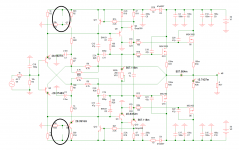
From your reports I could not figure out a problem in the design that might cause it to do what it did. First I thought the MOSFETs are fake, but it looks like they are not. Then after backtracking for sometime I found that a few days ago the LEDs were placed in reverse (effectively absent in the circuit) and the amp was given power (post#1606, post#1617).
So I simulated it to check what fault condition may occur with the LEDs not present in the circuit. The readings are well in the red zone! Check the attachment.
With the LEDs absent, the current sources go out of control, the input pair is passing about 20 times their normal bias current, the VAS buffer is passing about 50 times and VAS stage (and VR1 trimmer) passing about 55 times. Real world readings will vary somewhat but will be similar, and if that doesn't cause the components to let off smoke immediately it may cause some internal damage to some of the overloaded components so that they work normally for some time and when conditions such as load or temperature changes they start working out of their specifications. Exactly which way this may have caused the MOSFETs to blow is hard for me to say without direct probing, maybe the high current degraded the conductive strip of VR3 or maybe something else, but I think this is what has happened in your case.
...
It is recommended that you check each transistor, possibly after desoldering them from the board, or better just replace the whole set, as after such faults sometimes they read fine in a meter, but fail in the circuit. Also measure all the resistors and replace the ones that seem to deviate from their values, that includes the three trimmers.
Hope this helps and bests.
I have abused the amp (particularly after rev2 mod) so much, so many times, in so many ways that unless something was seriously wrong, like a fake or misplaced component, it just works.
From your reports I could not figure out a problem in the design that might cause it to do what it did. First I thought the MOSFETs are fake, but it looks like they are not. Then after backtracking for sometime I found that a few days ago the LEDs were placed in reverse (effectively absent in the circuit) and the amp was given power (post#1606, post#1617).
So I simulated it to check what fault condition may occur with the LEDs not present in the circuit. The readings are well in the red zone! Check the attachment.
With the LEDs absent, the current sources go out of control, the input pair is passing about 20 times their normal bias current, the VAS buffer is passing about 50 times and VAS stage (and VR1 trimmer) passing about 55 times. Real world readings will vary somewhat but will be similar, and if that doesn't cause the components to let off smoke immediately it may cause some internal damage to some of the overloaded components so that they work normally for some time and when conditions such as load or temperature changes they start working out of their specifications. Exactly which way this may have caused the MOSFETs to blow is hard for me to say without direct probing, maybe the high current degraded the conductive strip of VR3 or maybe something else, but I think this is what has happened in your case.
...
It is recommended that you check each transistor, possibly after desoldering them from the board, or better just replace the whole set, as after such faults sometimes they read fine in a meter, but fail in the circuit. Also measure all the resistors and replace the ones that seem to deviate from their values, that includes the three trimmers.
Hope this helps and bests.
Attachments
Last edited by a moderator:
If you have DMM (multimeter) measure your speakers and post the resistance from the speaker binding posts. That amp should barely break a sweat on anything 4-ohms and up, but if your speakers are 3-ohm or less you might be asking too much, especially at a higher volume.
i measured 4,7 ohm.
What did you put between these fets and heatsink as insulator?
in put some thermal rubber pads that i had at hand.
Hi Pistollero.
I have abused the amp (particularly after rev2 mod) so much, so many times, in so many ways that unless something was seriously wrong, like a fake or misplaced component, it just works.
From your reports I could not figure out a problem in the design that might cause it to do what it did. First I thought the MOSFETs are fake, but it looks like they are not. Then after backtracking for sometime I found that a few days ago the LEDs were placed in reverse (effectively absent in the circuit) and the amp was given power (post#1606, post#1617).
So I simulated it to check what fault condition may occur with the LEDs not present in the circuit. The readings are well in the red zone! Check the attachment.
With the LEDs absent, the current sources go out of control, the input pair is passing about 20 times their normal bias current, the VAS buffer is passing about 50 times and VAS stage (and VR3 trimmer) passing about 55 times. Real world readings will vary somewhat but will be similar, and if that doesn't cause the components to let off smoke immediately it may cause some internal damage to some of the overloaded components so that they work normally for some time and when conditions such as load or temperature changes they start working out of their specifications. Exactly which way this may have caused the MOSFETs to blow is hard for me to say without direct probing, maybe the high current degraded the conductive strip of VR3 or maybe something else, but I think this is what has happened in your case.
...
It is recommended that you check each transistor, possibly after desoldering them from the board, or better just replace the whole set, as after such faults sometimes they read fine in a meter, but fail in the circuit. Also measure all the resistors and replace the ones that seem to deviate from their values, that includes the three trimmers.
Hope this helps and bests.
Hello Shaan i think you are right and could be that, on testing i powered both boards with the leds reversed... for a while... no a second..
i will try to troubleshoot this boards but i will also build new ones with your power supply also. I will send you pm.
do your power supply turn off the amp if the amp shorts or it works only if has dc on output?
with covid problems how is the shipping to portugal?
later i will post the schmematic and how a made the connections of my psu for you and others to see if is anything wrong that could damaged the amp.
The power supply has DC protection for the speakers, no protection for the amp modules. The MOSFETs are given basic protection for momentary short circuits with the SMD diodes but only as long as as the diodes themselves are not overloaded/damaged by the previous stage.
I will check with the PO for shipping status for Portugal as their online documents are mostly useless when it comes to published list of open countries vs reality check.
I will check with the PO for shipping status for Portugal as their online documents are mostly useless when it comes to published list of open countries vs reality check.
This is the schematic of the psu..
Is anything wrong?
The wires on the secondary of the transformer could be connected out of phase to the bridges??
My transformer only has 4 wires, 2 black, 2 white.
2x39v black, 2x39v white.

Is anything wrong?
The wires on the secondary of the transformer could be connected out of phase to the bridges??
My transformer only has 4 wires, 2 black, 2 white.
2x39v black, 2x39v white.
- Home
- Group Buys
- PeeCeeBee V4H GB