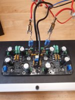
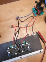
Hello,
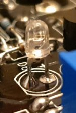
I m having problems, the leds on my boards did not lit up.
Before connecting everything i checked every board carefully.
Before connecting the power supply i checked continuity between the legs of the ics and heatsink. No continuity.
After connecting power supply and power up i have some continuity between the drain of the mosfets and ground/heatsink.
....i built a lot of amps and dacs even with smds etc.. never had problems...
Don t know where to start...


I only used two paralell per rail because i only had 5 resistors. Any problem?Hi Pistollero.
Those resistors can be paralleled, four on each side. I'd recommend four of the 1.8ohm per rail.
Continuity with heatsink is bad, did you use an insulator under each mosfets and transistor attached to the heatsink?
Also make sure the heatsink has a ground for it to the PSU.
Using two is only 4 watts, so make sure you keep it very low only for function testing or any power testing and they will burn very quickly
Also make sure the heatsink has a ground for it to the PSU.
Using two is only 4 watts, so make sure you keep it very low only for function testing or any power testing and they will burn very quickly
Yes they all have insulators.Continuity with heatsink is bad, did you use an insulator under each mosfets and transistor attached to the heatsink?
Also make sure the heatsink has a ground for it to the PSU.
Using two is only 4 watts, so make sure you keep it very low only for function testing or any power testing and they will burn very quickly
I did not connect the multimeter probes to r25 or 26 but i think it is not needed for the leds to shine or it is needed?
Heatsink is connect to 0v on power supply.
You have something wrong, check to make sure LEDs are correctly oriented first.
Next, with no power , check all pins/legs of the mosfets and transistors on the heatsink... continuity mode, black probe on heatsink - none of the pins/legs for the mosfets or transistors on the heatsink should would continuity.
If you hear a “beep” or see OL on your meter, do not power up, you must figure out which one is the issue and correct this issue before powering up.
Be sure you use the DBT until you are confident everything is working and no issues only then do you power up without the DBT.
I disconnected ps wires and checked all legs one by one to the heatsink i have no continuity, no beeps. Black probe to heatsink.You have something wrong, check to make sure LEDs are correctly oriented first.
Next, with no power , check all pins/legs of the mosfets and transistors on the heatsink... continuity mode, black probe on heatsink - none of the pins/legs for the mosfets or transistors on the heatsink should would continuity.
If you hear a “beep” or see OL on your meter, do not power up, you must figure out which one is the issue and correct this issue before powering up.
Be sure you use the DBT until you are confident everything is working and no issues only then do you power up without the DBT.
Checked the leds , i think they are ok.

Have you checked your power supply by itself w and w/o DBT to make sure it is giving you correct voltages you expect? Double check all wires with meter to make sure nothing is shorting.
I measured vcc 54v and vee - 54v with suppy connected..Have you checked your power supply by itself w and w/o DBT to make sure it is giving you correct voltages you expect? Double check all wires with meter to make sure nothing is shorting.
What you meen by DBT?
DBT=dim bulb tester, basically similar to your resistors in line with Vcc and Vee, but varies as the DBT lights up to limit more current as the short (or resistance) increases.
I would suggest putting together a DBT (Google will help) and get a 100w incandescent bulb.
Then recheck everything when you have it together with you meter for shorts. For this take out the resistors on the power rails, it might confuse the meter.
If any legs of outputs or drivers on heatsink show continuity, you need to figure that out.
You should not try anything until you have no shorts detected.
I m out but i have a dbt at home and i will test it.I would suggest putting together a DBT (Google will help) and get a 100w incandescent bulb.
Then recheck everything when you have it together with you meter for shorts. For this take out the resistors on the power rails, it might confuse the meter.
If any legs of outputs or drivers on heatsink show continuity, you need to figure that out.
You should not try anything until you have no shorts detected.
Hello, i removed the resistors, connected the DBT with a 60 watt incandescent bulb that was what i had at home.I would suggest putting together a DBT (Google will help) and get a 100w incandescent bulb.
Then recheck everything when you have it together with you meter for shorts. For this take out the resistors on the power rails, it might confuse the meter.
If any legs of outputs or drivers on heatsink show continuity, you need to figure that out.
You should not try anything until you have no shorts detected.
Before power up i checked every ic leg continuity to ground and no shorts.
Powered up and the bulb got bright than right after turned dim until off. Them i powered off but the leds on the board did not shine...
Hello, i removed the resistors, connected the DBT with a 60 watt incandescent bulb that was what i had at home.
Before power up i checked every ic leg continuity to ground and no shorts.
Powered up and the bulb got bright than right after turned dim until off. Them i powered off but the leds on the board did not shine...
Are you sure for the value of R19, R20?
Yes just measured right now - 33k both boardsAre you sure for the value of R19, R20?
Go slow, 1 channel at a time and use the DBT until you have consistent results then full power. Then do the same process with the other channel.
Then power it up with both channels straight power and have your hand on the plug in case any thing smokes or gets too hot, monitor for at least 30 mins before you think about leaving it unattended.
Then power it up with both channels straight power and have your hand on the plug in case any thing smokes or gets too hot, monitor for at least 30 mins before you think about leaving it unattended.
[emoji106]vas biasing done in one board and offsett trimming also.Go slow, 1 channel at a time and use the DBT until you have consistent results then full power. Then do the same process with the other channel.
Then power it up with both channels straight power and have your hand on the plug in case any thing smokes or gets too hot, monitor for at least 30 mins before you think about leaving it unattended.
For the mosfets... since i dont have the resistors now connected(2x1.8ohm paralell).. i don t know how to do it.. maybe tomorrow i will buy 1ohm resistors... and continue.
I have 0.9ohm...is the same value for mosfet biasing?
Also need to desolder the leds on the second board also and reverse.....
I would have to read the setup guide but just replace 0.9 for the 1 ohm (assuming) in the guide. That 0.1 difference will not make a big difference, it will be slightly higher at 0.9 vs. 1.0, so go 1-2mV less that the guide voltage to be safe.
- Home
- Group Buys
- PeeCeeBee V4H GB