Hi all!
Help, please, in the V4H setup. I do the following:
- unscrewed VR1, VR2 to maximum, VR3 to zero.
- jumpers open
- the entrance is open
I connect to a laboratory two-channel power source (/ -30V), the multimeter shows a drop of 770mV at R25 and 640mV at R26. LEDs are on. The output voltage is -25.92V. The power source shows a current of 30-40mA for each channel.
Rotation of VR1 and VR2 gives nothing, the voltage on R25 and R26 only increases by units of mV.
Similarly, it happens on another board. What to do, where to look?
Hi Birden.
Check all the BJTs whether they were placed in correct places. What is the LEDs' voltage rating? Is the heatsink shorted to ground?
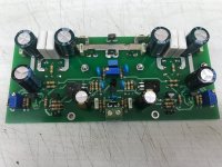
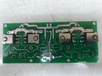
Please share a couple pictures of your setup if possible.
Check all the BJTs whether they were placed in correct places. What is the LEDs' voltage rating? Is the heatsink shorted to ground?
Please share a couple pictures of your setup if possible.
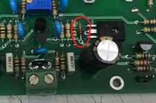
I think I found a problem - D4 is soldered in reverse )
I'll fix it tomorrow
I'll fix it tomorrow
Attachments
Last edited:
I turned the diode, it all worked.
There is a discrepancy between the scheme and the board - D4 and R10 are swapped. In the original placement of the D3 cathode up the board, D4 cathode down the board. In my version of the redrawn board, both diodes should be cathodes up, but I assembly the my board according to the original placement )
PS. Many thanks to the author for his hard work! This is my first amplifier.
You have a different board than I do , BUTI think I found a problem - D4 is soldered in reverse )
I'll fix it tomorrow
According to the silk the diode is installed the right way. But according to the schematic ...... you are right. Diode D4 should be reversed.
Thank you for your sharp eye, I had similar problem , 0.8v and couldn't adjust , so I kind of temporarily abandoned the project. I wonder if anyone else had this problem.
I think I found a problem - D4 is soldered in reverse )
I'll fix it tomorrow
I turned the diode, it all worked.
There is a discrepancy between the scheme and the board - D4 and R10 are swapped. In the original placement of the D3 cathode up the board, D4 cathode down the board. In my version of the redrawn board, both diodes should be cathodes up, but I assembly the my board according to the original placement )
PS. Many thanks to the author for his hard work! This is my first amplifier.
Everything is set correctly, everything is already working fine. Now I will assmbly the PSU )
I'm glad you already solved the issue. 🙂
Happy building
Update: Group Buy for Rev1 V4H boards is online!
Interested members please leave post with their required number of boards.
Thanks.
shaan
Interested members please leave post with their required number of boards.
Thanks.
shaan
Update: Group Buy for Rev1 V4H boards is online!
Interested members please leave post with their required number of boards.
Thanks.
shaan
Hi Shaan,
I like 4 boards please.
You have a different board than I do , BUT
According to the silk the diode is installed the right way. But according to the schematic ...... you are right. Diode D4 should be reversed.
Hello Shaan,
Has D4 been a problem for others? I am nearing completion of populating the boards but would like to solder everything correctly before I start testing it. Thank you!
Bao
Hi Bao.
In my schematic and boards every component is oriented correctly - d3's negative to q3's base and d4's positive to q4's base, with r9 and r10 in series. In a series connection it doesn't matter whether a component is placed before the other or after. Birden placed the diodes in reverse in his boards.
In my schematic and boards every component is oriented correctly - d3's negative to q3's base and d4's positive to q4's base, with r9 and r10 in series. In a series connection it doesn't matter whether a component is placed before the other or after. Birden placed the diodes in reverse in his boards.

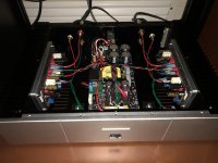
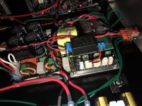
Finally got some time to add a small ac/dc power supply to the Cresnet SMPS1200-55 to enable the stand-by function. The veroboard looks to be floating in the picture, but it is supported from the backside also. Now the front mounted power switch is utilized instead of having to blindly reach around back for the main switch.
Attachments
@Vunce
The new SMPS units will have on board standby circuit, and many improvements.
Very nice build 😎
The new SMPS units will have on board standby circuit, and many improvements.
Very nice build 😎
- Home
- Group Buys
- PeeCeeBee V4H GB