I only have at home 5mm red LED, those are 2V type based on the general information. Can I use those or must be 1.8V (3mm) type?
If someone built the amp please share your opinion.
Thank you
Based on the picture some people use 3mm other use 5mm I even saw green 5mm types???
Hi Gabor.
You can use the 2V rated red LEDs without problem. However it may need only a couple turns in VR1 and VR2 to reach 10mA VAS bias, be careful during setup.
Guys (please) I really would love to get some help so I can put this project together, please🙄
Very likely Shaan is sick, I know other peoples finished these project, what hard to understand the unwillingness to help 😕😱a fellow DIY-er. Honestly, if I can (able) to help someone I usually jump in to do so.🙂
I'm better than before but it's festive season here so giving my family some time and been wandering with them here and there. As a result could not find time to jump in. 🙂
I'm not an expert but try to help as much as I can. I hope it helps you setup your boards. Feel free to post any and all questions regarding the amp. If you want you can message me in FB too.
I having a problem to find the jumpers since there is no part number and I never used something like that before I do not wish to order some useless items. The shipping cost to me just too much to order unwanted parts.
If you can't find any 2.5mm pitched jumper header pins then use cut-off wires of the resistors, or any other wire. The jumpers need to be shorted only after setup has been done. If you don't want to or can't find jumper shunts then just solder the top of the two wires, will work without any problem.
Please, guys, I need some help!?😕😕
Maybe I'm impatient, maybe -(I suffer from PTSD and herniated low back problem, my spine pushes the nerve) These not for an excuse.
Nothing is ever taken as excuse, Come on! If it is hurting too much then I'd suggest that you don't push it too much, get back to assembling after you start feeling better.
Also, I ordered 1/2W resistor PRP type I suffered a lot to populate the boards, just found out I supposed to use 1/4W type.
Thank you.
Greetings gabor
That's unfortunate (However, don't desolder them if one's pins are not touching another resistor's pin. Don't worry the amp will work fine with either 1/2 or 1/4w resistors.
Thanks for your patience.
Hi Gaborbela, or anyone looking for a PN from the BOM published , example:
- for the 6.35mm x 0.8mm terminal tab : 1217127-1 TE Connectivity / AMP | Mouser Romania or Mouser PN : 571-1217127-1, I would sugest to use these kind because of the kinked tabs found on each side making them more friendlier to the solder joint (these two on each side will push on the PCB so the tension will go on the laminate if soldered right at the surface of the board ) when inserting the female header on.
- example of jumper header cap of 2.54mm from Mouser : 1-881545-2 TE Connectivity / AMP | Mouser Romania , or Mouser PN : 571-1-881545-2, if you need more example just search in the category that this one is found ;
Again if you need the male or female one, just tick the desired type from the selection boxes , usually you can get these from many supplier not just mouser, I get stuff from mouser, or TME, you will find these more or less under the same category.
Cheers.
Last edited:
Hi Shaan, what's with the 12mm straight pin header - 6 of these in the BOM, I have looked at the PCB layout and I only see the power connectors, the input one, output one and that's about all.
Thank again.
Thank again.
Thank you, Shaan & Oracle1
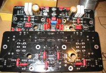
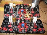
Here is my progress, it was not easy because of the size of the resistors I ordered. I usually use 1/2W type and automatically I order those. I did not want to return for exchange because of the shipping cost plus they take of percentage for restocking.
I soldered some part on the bottom I could not do another way.
I will order some parts more (some electrolytic) the one I got way too big by size. Nichicon FG 2200uF 25V or ROE 2200 16V.
No problem because I need a few other things also.
Can I use this for a jumper? I do not see legs for soldering.
Sorry, this part is new to me. I don't know how this works, it supposed to have another part like male and female?
M7581-05 Harwin | Mouser Canada
If this OK I will order form Mouser together the other missing parts.
Please let me know, thank you! 🙂
🙂
Greetings gabor
Here is my progress, it was not easy because of the size of the resistors I ordered. I usually use 1/2W type and automatically I order those. I did not want to return for exchange because of the shipping cost plus they take of percentage for restocking.
I soldered some part on the bottom I could not do another way.
I will order some parts more (some electrolytic) the one I got way too big by size. Nichicon FG 2200uF 25V or ROE 2200 16V.
No problem because I need a few other things also.
Can I use this for a jumper? I do not see legs for soldering.
Sorry, this part is new to me. I don't know how this works, it supposed to have another part like male and female?
M7581-05 Harwin | Mouser Canada
If this OK I will order form Mouser together the other missing parts.
Please let me know, thank you!
🙂Greetings gabor
Attachments
Hi Gaborbela, you can use the one you are showing as the jumper cap, you need also the one that solders to the PCB, for example from Mouser you can get this made by TE Connectivity , part number is 825433-2.
Good luck.
Good luck.
Last edited:
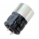
By the way ...
... You are not wrong. This is a industrial type of an ELNA capacitor !
Yes , not bad Kane
... You are not wrong. This is a industrial type of an ELNA capacitor !
Attachments
Hi Gabor,
I like PRP resistors (not attracted to magnets).
I assume that you know that you have to clean off the flux on the boards after soldering.
I use alcohol with a tooth brush. Usually I do it before soldering the trimmers and electrolytics.
PS I prefer 1/2W resistors.
I like PRP resistors (not attracted to magnets).
I assume that you know that you have to clean off the flux on the boards after soldering.
I use alcohol with a tooth brush. Usually I do it before soldering the trimmers and electrolytics.
PS I prefer 1/2W resistors.
I like PRP also, not magnetic and low distortion type.
https://www.partsconnexion.com/media/pdfs/prp.pdf
I will clean it before I mount the power MOSFETs.
Usually, I use acetone in the same way as you with a toothbrush, of course, I test it first not to remove the solder masks.
https://www.partsconnexion.com/media/pdfs/prp.pdf
I will clean it before I mount the power MOSFETs.
Usually, I use acetone in the same way as you with a toothbrush, of course, I test it first not to remove the solder masks.
I have never used acetone. Might be too harsh?
Be careful that it does not get into the trimmers and electrolytic caps ie into the seals of these components.
I usually clean the board after I have soldered the resistors, as they are more robust. Then I do a touch up clean for the remaining components.
Keep us posted on your progress.
Be careful that it does not get into the trimmers and electrolytic caps ie into the seals of these components.
I usually clean the board after I have soldered the resistors, as they are more robust. Then I do a touch up clean for the remaining components.
Keep us posted on your progress.
The best is isopropole. Not alkohol, neither acetone. That will make the pcb stick and looks ugly!!! Isopropole cleans also vinyl !
Vinyl records i ment
That is alcohol also.
Acetone if it used with care it does do a very good job.
You do not need to worry it evaporates very fast. Of course, I use just a little with a soft toothbrush, I do not soak it or make a bath to the board.🙂
If it needs I repeat it until totally clean and stick no longer.
I use clean acetone, not a nail polish remover! That junk just makes a mess.
Remember not the acetone if you use clean acetone, sticky the flux is.
I learn that in a TV shop from an old fellow.
I'm looking to purchase transformers for this build. asuslover had previously recommended staying under 40vac secondaries in PeeCeeBee V4H GB. Any reason to do this? It seems like 40vac would be a good rail voltage for maximum swing: 40*1.414 = 56.56vdc (will be a little under given diode and CRC drop).
Also to confirm, would 300va per channel at 40vac (7.5A) be a good sizing for the V4H?
Thanks!
Greg
Also to confirm, would 300va per channel at 40vac (7.5A) be a good sizing for the V4H?
Thanks!
Greg
I'm looking to purchase transformers for this build. asuslover had previously recommended staying under 40vac secondaries in PeeCeeBee V4H GB. Any reason to do this?
With higher AC input the rectified DC goes too close to the max ratigs of the small BJTs; 40V is a safe ceiling.
Also to confirm, would 300va per channel at 40vac (7.5A) be a good sizing for the V4H?
Yes!
 🙂
🙂Thanks Shaan,
I think I'll be purchasing a pair of 40vac / 300va from Antek: AS-3440 - 300VA 40V Transformer - AnTek Products Corp. My brother (loafimus) had good results with these having the static shield on his V4 to reduce hum.
Greg
I think I'll be purchasing a pair of 40vac / 300va from Antek: AS-3440 - 300VA 40V Transformer - AnTek Products Corp. My brother (loafimus) had good results with these having the static shield on his V4 to reduce hum.
Greg
Hi Shaan,
The transformer I’m using for the V4H has 45v secondaries. I’m targeting 58vdc under load after CRC filter. Is that cutting to close to BJT’s max voltages?
Thanks
The transformer I’m using for the V4H has 45v secondaries. I’m targeting 58vdc under load after CRC filter. Is that cutting to close to BJT’s max voltages?
Thanks
I checked the specs, I will be fine with the KSE340/350. But close to the BC546/556’s max of 65v.
Question regarding mosfets install/soldering under the PCB:
Is it advisable to leave some empty space (1 or 2mm) between the face of the mosfets and the pcb ?
Any recommendation for the space between the lower side of the pcb and the heatsink for best ventilation / air flow ?
Thanks
JMK
Is it advisable to leave some empty space (1 or 2mm) between the face of the mosfets and the pcb ?
Any recommendation for the space between the lower side of the pcb and the heatsink for best ventilation / air flow ?
Thanks
JMK
- Home
- Group Buys
- PeeCeeBee V4H GB