Ajit - 2pc
steefdebruijn - 2pc
amitskamal - 1 full stereo kit with all components.
Neurotica - 2 PCBs
vvs07 - 4 PCBs
steefdebruijn - 2pc
amitskamal - 1 full stereo kit with all components.
Neurotica - 2 PCBs
vvs07 - 4 PCBs
Thanks Shaan your kindly reply.
Your info is invaluable.
Somehow i find few circuit design will use individual frontend psu . However i am not sure how the best to the sound and what listening feel would be changed. So i want to do a trial and compare. Anyway diy is like my this behavior. 😀
Your info is invaluable.
Somehow i find few circuit design will use individual frontend psu . However i am not sure how the best to the sound and what listening feel would be changed. So i want to do a trial and compare. Anyway diy is like my this behavior. 😀
Ajit - 2pc
steefdebruijn - 2pc
amitskamal - 1 full stereo kit with all components.
Neurotica - 2 PCBs
vvs07 - 4 PCBs
outtek - 2 PCB and power mosfet kit for the two boards (invoice received and paid)
steefdebruijn - 2pc
amitskamal - 1 full stereo kit with all components.
Neurotica - 2 PCBs
vvs07 - 4 PCBs
outtek - 2 PCB and power mosfet kit for the two boards (invoice received and paid)
Hi Outtek.
The invoice I sent is for shipping charge for the PSU board scheduled for shipping soon.
I haven't started sending v4h invoices for GB2 yet. Will update here as soon as I do.
The invoice I sent is for shipping charge for the PSU board scheduled for shipping soon.
I haven't started sending v4h invoices for GB2 yet. Will update here as soon as I do.
Ajit - 2pc
steefdebruijn - 2pc
amitskamal - 1 full stereo kit with all components.
Neurotica - 2 PCBs
vvs07 - 4 PCBs
outtek - 2 PCB and power mosfet kit for the two boards
steefdebruijn - 2pc
amitskamal - 1 full stereo kit with all components.
Neurotica - 2 PCBs
vvs07 - 4 PCBs
outtek - 2 PCB and power mosfet kit for the two boards
Last edited:
Hi Patrick.
For V4H +/-56V PSU with at least 10,000uF per rail is good for one channel.
Hi Shaan,
working backwards this would mean a toroidal transformer with secondary windings at 40VAC-0-40VAC. (giving a rail voltage of approx 55.6VDC)
I just want to confirm that I can use the 63VDC rail capacitors ie 10000uF in the PSU, or do I need to go to a higher capacitor voltage rating.
kind regards
stevet
silicon diodes for full wave rectification say 0.6V x 2, so the voltage drops by 1.2V.
so now 55.4VDC-ish.
Thanks Pieter, I should have thought more about it.
so now 55.4VDC-ish.
Thanks Pieter, I should have thought more about it.
Don't forget B of the transformer. Mine have a given and measured B of 1.08 so I have to start calculating from 40V * 1.08 = 43.20 V.silicon diodes for full wave rectification say 0.6V x 2, so the voltage drops by 1.2V.
so now 55.4VDC-ish.
Thanks Pieter, I should have thought more about it.
Results f.e.g. in 43.2V * 1.414 = 61.08V - 1.2 V = 59.88 V (without load).
(Also my diodes differ from fact-sheet: given 0.72 V so I should have 1.435 V. But measured 1.54 V.)
Simulated load of the whole PSU with power-resistors results in a voltage drop of 5.7V.
So I would get 59.88 V - 5.7 V = 54.18 V if the mains-voltage of 230 V would not vary from 207 V to 253 V (± 10%).
So theoretical I can get the min. value or the max. value:
min.: 48.76 V (-10%) / max.: 59.6 V (+10%).
Hi, Shaan, just ship my PSU board in that case, I will have something to do during this time 🙂).
Thanks.
Thanks.
are there some pics of finished amps here?
🙂
And maybe some listening impressions too..
Attachments
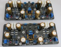
Getting close 😉
looks good.
can´t wait to see finished amps and read about the listening impressions...
- Home
- Group Buys
- PeeCeeBee V4H GB