Just reading through the bias trimming section again, but should the bias be set by red to TP3, black to ground, red to to TP4, black to ground etc. rather than red to TP3, black to TP4? If that is the case, do we adjust to 200mV per TP and GND or 100mV for each?
Output stage quiescent current or bias is to be measured through R59 and R60 for each channel. TP3 and TP5 are connected to one leg of R59 and R60, and TP4 and TP6 to the other leg. So when measuring bias, you need to probe across these resistors only (or their negative mirrors R61/R62). During bias measurement we only need the absolute value of the measured voltage (and divide by R59/R60 value to get current in milliamps), polarity is not important. So you can connect the probes in any way you want.
TP4 and TP6 are output nodes, just on the left of C27/28. And during offset measurement connecting the black probe to ground and red probe to TP4 or TP6 gives us the exact polarity of the output offset voltage. Reversing the probe polarity is not an issue at all, you will only need to turn the trimmers the opposite way than what is suggested to trim the offset close to zero.
TP4 and TP6 are output nodes, just on the left of C27/28. And during offset measurement connecting the black probe to ground and red probe to TP4 or TP6 gives us the exact polarity of the output offset voltage. Reversing the probe polarity is not an issue at all, you will only need to turn the trimmers the opposite way than what is suggested to trim the offset close to zero.
Last edited:
Hi Hydrovac.
I am assembling the module orders now. Modules starts shipping from this Thursday.
Hi Shaan,
Do you have any updates on shipping of modules?
Thanks for the explanation Shaan.
I get no reading across either R59 or R60. I had a check across the board last night for shorts but couldn't see anything obvious (I'd cleaned the board well with isopropyl alcohol before setup), so I'll have another look later.
I get no reading across either R59 or R60. I had a check across the board last night for shorts but couldn't see anything obvious (I'd cleaned the board well with isopropyl alcohol before setup), so I'll have another look later.
Hi Shaan,
Do you have any updates on shipping of modules?
Shipped. Tracking ID sent via PM.
Thanks for the explanation Shaan.
I get no reading across either R59 or R60. I had a check across the board last night for shorts but couldn't see anything obvious (I'd cleaned the board well with isopropyl alcohol before setup), so I'll have another look later.
VR1,2,3,4 need more clockwise turns, that's all. 🙂
I had tried that, that's why I think I've got something wrong somewhere. I'm going to check orientation of all parts and a real close look for shorts (it's happened before with me, I often make a silly mistake).
Hi Shaan,
No luck I'm afraid.
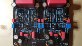
I cleaned the underside of the board again and gave it a good close inspection, no shorts that I can see.
No luck I'm afraid.
I cleaned the underside of the board again and gave it a good close inspection, no shorts that I can see.
- All capacitors are correct for polarity
- All diodes are correct for polarity
- The small transistors are correct in orientation and placement
- BD139 and B140 are correct in orientation and placement
Hi Neal.
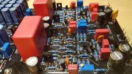
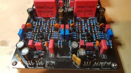
A couple close pictures would be helpful.
Check all BJTs' base-emitter and base-collector continuity in diode test mode with power removed.
A couple close pictures would be helpful.
Check all BJTs' base-emitter and base-collector continuity in diode test mode with power removed.


Finally had time to look at this again.
Testing a BD139, no power applied.
Positive probe to B gives 0.7V at C and E. Negative probe to B gives 1.8V to C and 0.7V to E.
I know the negative to B should give OL readings when you measure them out of the circuit, does that still apply in circuit?
Testing a BD139, no power applied.
Positive probe to B gives 0.7V at C and E. Negative probe to B gives 1.8V to C and 0.7V to E.
I know the negative to B should give OL readings when you measure them out of the circuit, does that still apply in circuit?
Negative probe to B + positive probe to C shows Q13's base-collector voltage plus the drop around R17 and R43 in series. Negative probe to B + positive probe to E just shows the drop around R47.
If it is showing 0.7V B-E and B-C with positive probe to B then the BJT is okay.
edit: short base to emitter with a wire and probe collector-emitter voltage drop, should show infinite if it is really okay.
If it is showing 0.7V B-E and B-C with positive probe to B then the BJT is okay.
edit: short base to emitter with a wire and probe collector-emitter voltage drop, should show infinite if it is really okay.
Last edited:
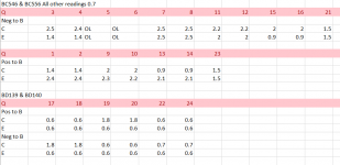
As far as I can see, nothing stands out. If a junction was open or short it would show up in here. And to me it looks like all the BJTs are okay!
Have you measured all the resistor? Also check whether the trimmers' resistance is responding to turning the screws.
Btw, did you turn the trimmers right to maximum clockwise turns and still found no reading across R59/60? Depending on BJT hFE the trimmers sometimes need more turns to turn on the bias.
Well, I thought I'd turned the trimmers most of the way out, but I hadn't.😱
This time I counted, at 30 x 1/2 turns - nothing. 40 1/2 turns and I got a reading of c.70mV. I'm not sure how many turns it was after that to get to 200mV, I'd stopped counting because I was so relieved, but it wasn't many.
Offset tuned to 1mV so it's ready for testing, unfortunately I don't think I'm going to get a chance to hook it up and test for a few days now.
Thank you Shaan, once again your patience with this idiot is very much appreciated.
I will remember your postings Neal for when I do my build. No harm done though, so all is good.


![20200909_180602[1].jpg](/community/data/attachments/804/804745-329d1331c8e54ef38092395922b34dd9.jpg?hash=Mp0TMcjlTv)
- Home
- Group Buys
- PeeCeeBee Preamplifier GB