Yeah that tranyore circuit is trying to power the sense circuit with 120 vac. Considering your AC or furnace motor puts 1300 V spikes on the AC line, no wonder the TO92 transistors blew up. At minimum needs a MOS spike supressor after a fuse on the transistor side. (MOS fails short, needs a fuse). Also 600 v rated TO92 transistors anyway.
That 30 lb transformer does the spike supression on the Peavey side. Reason all switcher supplies worth the salt to blow them up have a MOS supressor. The blue thing on the board.
That 30 lb transformer does the spike supression on the Peavey side. Reason all switcher supplies worth the salt to blow them up have a MOS supressor. The blue thing on the board.
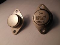
I would be skeptical just based on price. Real ON Semi are about four bucks. Try the easy things first. Acetone on the lettering. Real ones it stays, fakes it comes off. Try gripping the top hat with a pair of pliers and giving it a gentle twist. Real ones cannot be removed this way (you need to resort to a hacksaw) and fakes come right off. Measure vbe. The last batch of fake 15024’s I had they were all different - as in not matched and suitable for paralleling, despite the same date code. Real ones will be close enough right out of the tube within a handful of millivolts. Upon popping the tops off (which was easy) I discovered that they didn’t even use the same dies in the batch. Some were even genuine ON dies - but older types (2N5631 family) but mounted improperly. A few were the size of a TIP41, it most were 2N3055-ish. ALL of them passed a 200 volt VCEO. You can test this non destructively easily using a 5mA current source you build out of an MJE350 and your amp’s power supply.
The real test is the SOA. 80 volts at 2 amps. Resort to this if it passes everything easy and you don’t want to chance ruining a good one with a hacksaw. Mount it on a big heatsink using a regular TO3 socket and thermal grease. Use a long-finned heat sink so you can lay the fins in ice water if it isn’t huge. Build a 2 amp current source out of it and hook it up to an 80 volt supply. Use current limited lab supplies or use a 4 amp quick blow fuse. Fakes wil die very quickly if not instantaneously. Real one will hold as long as Tc can be held near 25C which is why I like the ice water trick.
The real test is the SOA. 80 volts at 2 amps. Resort to this if it passes everything easy and you don’t want to chance ruining a good one with a hacksaw. Mount it on a big heatsink using a regular TO3 socket and thermal grease. Use a long-finned heat sink so you can lay the fins in ice water if it isn’t huge. Build a 2 amp current source out of it and hook it up to an 80 volt supply. Use current limited lab supplies or use a 4 amp quick blow fuse. Fakes wil die very quickly if not instantaneously. Real one will hold as long as Tc can be held near 25C which is why I like the ice water trick.
Well, thanks for the advice, even if it's bad news...Always a skeptic, I thought acetone would take off everything but here is an old ON semi TO3 beside my 'new' ones. The old ones were wiped repeatedly, the new ones---one pass! I will have another coffee and then check the Vbe.......This could be one of the most expensive mediocre amps yet!
Kahlua, anyone?
Kahlua, anyone?
Attachments
OFF WITH THEIR HEADS!!!
Ok, pop the cover, let’s see what’s inside. If it doesn’t even pass the acetone test you have nothing to lose.
Unless of course you want to build an amp in which those transistors will actually work. It can be done, just requires more of them in series-parallel. Assuming you can get a rough match in groups of three or four.
I’d trust the old ones more at this point. Or even those 15003 if measured Vceo is above 200V. The modern 2N3773 is a 15003 die tested to a different spec, and most of them are good for over 200V. I’m sure the original house numbered PV part (SJ43 something or other) was just a selected 2N3773 because the 15024 hadnt beeen invented yet and Motorola didn’t make the 2N6259.
Which brings me to something funny/fishy I saw on the Newark site. Pull up the data sheet for the Multicomp 2N6259, and you get what is clearly an MJ15024 data sheet. The $64,000 question is what do you get, and is it any good.
Hi Indianajo;
I'm afraid I'm in the power transistor testing mode, the fan control will have to wait. This amp won't be pumping out much heat for some time!
wg_ski;
I honestly had one between vice-grips and channel-locks----But could I do that SOA 2 amp/80 Volt test first? The MJE350 current source is a little beyond my knowledge at the moment. I have been 'googling' transistor checking circuits again. Do you have a link for the set-up you describe?
Could I use the CS800 supply, as you mentioned, with a variac . Then use a (10 ohm or lower?) resistor in series with the collector to monitor the Ic. I could use one of the CS800 heat sinks, which are empty at the moment. I could even submerge the fins in ice water, but from the sound of it, it won't have time to get hot. Can I use a pot to control base current/ Ic? You can see I am a real noobie!
I will send pics of an opened trans, asap, but the Vbe seems to be matching fairly well.
I am not yet at the 'acceptance' part of the grieving process! Thanks guys, don't let me interfere with you Christmas Cheer.
2 a ccs -
on a npn part, acquire a 220 ohm resistor, a common diode, a .35 ohm 1 watt or more resistor. Put 220 ohm series diode non-line, connect diode line to - PS, connect 220 ohm to + supply . connect MJ21196/4 emiitter to .35 ohm resistor, other end to - supply. connect MJ21196/4 collector through 10 a socket on dvm to + supply.
for 80 v soa test at 2 amps, use 80 v supply. Like the cs800. If you put a 4 a fuse in between the meter & the + supply you will blow it instead of the 10 a fuse in the meter if you short something.
when the DUT (device under test) leaks enough current to flow 2 amps, the emitter resistor drops .7 v and equals the diode drop. So the base stops cramming more current in the DUT.
My Christmas is done, played piano for the charity dinner 75 minutes today. One person, a 12 y.o. noticed & thanked me. Now just listening to the fm radio. St Olaf college is reading the same passages the minister read this AM. Their choir is better than ours, though.
Last edited:
I would do low current tests first and work up to high power. A 5mA ccs can be built using two diodes and a 100k resistor to bias an MJE350 or MJE5852 with a 120 ohm emitter resistor. This is a very useful tool in general, for anything from grading generic or unknown transistors to decoding zener diodes that the markings have worn off of.
For a high current ccs for SOA testing, you want a LOT more voltage on the emitter resistor, not just a diode drop. Bias the base with an isolated high current 14.4 volt supply and drop most of the voltage in the emitter resistor. 2 amps would need 6.8 ohms (at 30 watts). Any reasonable bias voltage and corresponding emitter resistor will work as long as it is much larger than vbe. This just happens to be convenient. Apply Vcc between collector and base. Turn it up with a variac and see if it holds at 80 volts for at least a few seconds. Turn it up slowly, and the current should be rock steady where you set it with the voltage across Re. If you used a lab supply limited at just a bit more, say 2.2 amps, you may be able to catch thermal runaway as it happens and save a (fake) transistor from destruction. There is an old RCA app note on how to build a non-destructive SOA tester using this same circuit, except that it uses a latch which shuts down Vcc in a couple microseconds if it senses thermal runaway. It did that by measuring a rapid drop in Vbe caused by the temperature rise.
For a high current ccs for SOA testing, you want a LOT more voltage on the emitter resistor, not just a diode drop. Bias the base with an isolated high current 14.4 volt supply and drop most of the voltage in the emitter resistor. 2 amps would need 6.8 ohms (at 30 watts). Any reasonable bias voltage and corresponding emitter resistor will work as long as it is much larger than vbe. This just happens to be convenient. Apply Vcc between collector and base. Turn it up with a variac and see if it holds at 80 volts for at least a few seconds. Turn it up slowly, and the current should be rock steady where you set it with the voltage across Re. If you used a lab supply limited at just a bit more, say 2.2 amps, you may be able to catch thermal runaway as it happens and save a (fake) transistor from destruction. There is an old RCA app note on how to build a non-destructive SOA tester using this same circuit, except that it uses a latch which shuts down Vcc in a couple microseconds if it senses thermal runaway. It did that by measuring a rapid drop in Vbe caused by the temperature rise.
Hi Indianajo;
Is this the test circuit you were describing? Have I interpreted it correctly? I was wondering if a larger resistor in place of the 220 ohm would work? At 80 Volts, this would dissipate about 30 Watts.
Is the base connected to the junction of the 220 ohm resistor and the diode?
Thanks Peter
Hi wg_ski;
I just checked, I just happen to have a high current 13.6 V regulated supply. I will study your advice above and try to sketch a circuit.
Thanks guys, Merry Christmas all!
Attachments
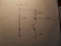
Yes, you have interpreted the circuit correctly, but the problem is that with such a low voltage across Re it is very difficult to get the target current correct without jacking around with it. Jacking around with it is how accidents happen.
yeah, forgot to connect top of diode to base of transistor.
Since Vbe of a real MJ21196 is lower than 0.7, you may have to put a pot across the diode to get Ic up to 2 amps.
I'd put a switch on the power supply to limit test time to 1 sec like the soa chart.
I'm using 2 diodes stacked to the base of the output transistor on a 4A bicycle 48 v battery charger I built. There are two NJW3281 and a .5 ohm collector resistor on each to balence the current. I'm using a 511 ohm 10 w pull up resistor. Will produce less than 2 amps if the battery doesn't want it. Will limit current to 2 amps per transistor if the battery is shorted. There is a stack of zeners reaching 54v above the 511 ohm resistor, that will stop conducting when the battery reaches 56 v. Current source to collectors is a bridge off a 47.5 v transformer. I charged the battery once, it didn't blow up.
Speaking of money savers with real ON parts, you can use TO264 or TO247 instead of TO3 on a Peavey heat sink. You have to cut the corners off the tab to make them fit. I use the selector part of the Newark website to see what the cheapest high watt transistor they are selling that day. They mix in the darlingtons, so be sure to screen those out yourself. That is how I ended up with NJL3281, they were demonstrators or something. Be sure to use the mica washer kits with the little plastic ferrules that keep your bent legs from touching the heat sink.
Last edited:
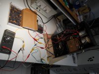
Good Morning Folks, A Test Circuit is Born--maybe!
Against good advice, I have been 'jacking around'. I used a variac and slowly raised the B+ voltage in increments. I used a switch (the 2 red alligator clips pointed to by the pencil) to keep the 'on' time just long enough to get a current reading on the Fluke meter. With the original circuit, I found very little increase in Ic, as Vbe increased. I assumed (and that's always dangerous) that with a .47 ohm emitter resistor and only one diode ( .7 V on the base ), the DUT was still cut off. With 2 diodes in series, Ic was .67 Amp at approx 75 V.
Against good advice, I have been 'jacking around'. I used a variac and slowly raised the B+ voltage in increments. I used a switch (the 2 red alligator clips pointed to by the pencil) to keep the 'on' time just long enough to get a current reading on the Fluke meter. With the original circuit, I found very little increase in Ic, as Vbe increased. I assumed (and that's always dangerous) that with a .47 ohm emitter resistor and only one diode ( .7 V on the base ), the DUT was still cut off. With 2 diodes in series, Ic was .67 Amp at approx 75 V.
Attachments
BTW; I Vbe tested all the 'fake' transistors and found them mostly around .610 to .622 V, (a couple were outside this) I would have no problem finding banks of five, that are matched to 1%). As mentioned, 2 series diodes got Ic to .67 A. What about 3 or 4 (or more diodes) to get Ic to 2 amps.
2 Amps at 80 V, that's 160 Watts! Isn't that kind of a tough test? Although, they are rated at 250 Watt. Opinions on just submerging the DUT in ice water, and keeping the test time just long enough to get a reading?
2 Amps at 80 V, that's 160 Watts! Isn't that kind of a tough test? Although, they are rated at 250 Watt. Opinions on just submerging the DUT in ice water, and keeping the test time just long enough to get a reading?
Attachments

Mount a TO3 socket on a heat sink for these tests. While a transistor will take a 1 second test without any one (that’s how they are tested at the factory), the chances of something coming loose and shorting out are pretty high.
2 amps at 80 volts is a tough test, but MJ15024 is supposed to be able to take it. If Tj can be kept below 200C. At that power level that would be a case temp of about 85C. 1 second without a heat sink probably doesnt heat it more than that, but if you accidentally left it on 10 seconds all bets are off. If you used a heat sink in ice water you could leave it running till the water starts to heat up.
Even if these units turn out to be fakes or copies, you may very well have gotten a good batch (as in useable in a CS800). It will be interesting to see of they pass the full SOA test. The fake batch of 15024’s I had were working just fine in the application - six in series/parallel on +/-125V rails with an 8 ohm load without failing. What bothered me was the unequal current sharing due to the wildly different Vbe - much worse variance than your batch. Long term that would have been an issue.
If you want more test current, leave 2 diodes but decrease emitter resistance. Definitely use a heat sink. Foot long piece of window frame from the garbage, anyway. Use Be grease.
Partial victory on your HK purchase. Not too bad Vbe match. Peavey CS800 with the .5 ohm emitter resistor does not need extreme matching. If you're not running a outdoor beach bar, time spent at 400 w/ch is pretty low anyway. soa may not matter much.
My end of bin starred discount $3 Newark MJ21195 were Vbe .457 .464 .472 .474 .477 so definitely not all out of the same packing tube.
Last edited:
Hi Folks;
I have some ON Semi MJ21196 outputs on order from Hong Kong ( Yikes?!!)!
Exactly !
I have been caught out a few times with fake semiconductors.
Too many times to get caught out again.
Buy cheap buy twice ! second time from a reputable dealer.
RS Components or Farnell are two ways to go who I know are reputable dealers.
Newark is Farnell US. His HK transistors have tighter Vbe match than I got from * bargain ON parts at Newark.Exactly !
Buy cheap buy twice ! second time from a reputable dealer.
RS Components or Farnell are two ways to go who I know are reputable dealers.
RS doesn't operate in the US. except Radio Shack, which is worse than HK for garbage. Other authorized ON distributors are Mouser and Digikey.
Hi Folks;
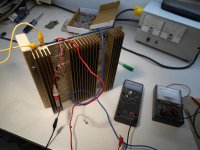
Well, I guess I'll be buying twice! I took the good advice and built a test rig from a CS400 heatsink and power pcb. With some 'jacking around', I found that I could get 0.6 amp at 80 V with one diode and 0.165 ohms of emitter resistance (two .33 resistors in parallel). I was using an aluminum Peavey transistor as a guinea pig.
The moment of truth; the MJ21196 was installed---curent went up to about 1.5 amps, and then POP! Here is the test rig
Attachments
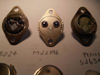
Notice how much easier it was to take the lid off the fake. I doubt the seal is even hermetic like it is supposed to be (hence the die-coat compound). And another suspicion confirmed - that SJ6343 is a 2N3773 (or at the very least a very close relative).
- Home
- Live Sound
- PA Systems
- Peavey CS800 Doorstop to Decent