Rich - The circuit behaves like the potentiometer is the wrong value. Please would you verify that it is a 5 kohm potentiometer you put in. It might be worthwhile removing and testing it. Do you have a spare one ?
We want 0 v at the P1 test point...
Pierre
We want 0 v at the P1 test point...
Pierre
Thanks Pierre ,
will do . I did and it checks out perfect ...Clicks at 5.18K
Rich
will do . I did and it checks out perfect ...Clicks at 5.18K
Rich
Last edited:
found the answer in post 555. Sorry.
James
James - Yes, these NJR parts are the ones that Wayne listed in the article. I remember them having a lower noise specification than those made by other manufacturers. My Pearl 2 is very quiet with them.
Pierre
Last edited:
Thanks Pierre ,
will do . I did and it checks out perfect ...Clicks at 5.18K
Rich
Oh well... sorry about the trouble. Perhaps some pictures might give us a clue?
You are sure you cannot adjust the P1 test point to zero with the potentiometer?
The lowest that pad will go is 10 volts? Are you sure it is not -10 volts? It is a very sensitive adjustment. Quite easy to miss the 0 volt and overshoot into the negatives... Note that +/- 0.1 V would be close enough.
Pierre
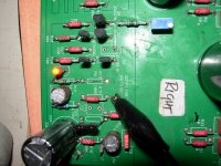
good picture ..... but problem is that all solder joints looks older than I saw on some tube amps from yore time
in this moment I'm doubting that you didn't scorched even some passive part , besides active ones ........
in this moment I'm doubting that you didn't scorched even some passive part , besides active ones ........
good picture ..... but problem is that all solder joints looks older than I saw on some tube amps from yore time
in this moment I'm doubting that you didn't scorched even some passive part , besides active ones ........
I hate to say it, but it is also the way the pic looks unfortunately.
There's either a problem with soldering technique, flux and/or soldering station usage. Sometimes older stations iron endpoints do not work well with unleaded. Sometimes temp is set too high, unadequate to the flux used and it can nick some active and even passive parts. Are you sure you do clean the iron end with a wet sponge or metallic equivalent between each solder point ? The endpoint should be perfectly clean and shiny between each solder point with no residue, black or even gold one. When I power up station, once temp is reached I always "clean" the endpoint by adding some fresh flux, and letting it burn for seconds before cleaning the endpoint perfectly with the wet sponge. Then my solder session can begin.
Could you post us pics of an other amp you made ? Do the joints also look like in the pic you just sent ?
Again, I hate to say. But some errors couldn't be corrected if the work is faulty.
Best regards,
nAr
Last edited:
The amp I made is on loan at the moment .... I use a wetting compound and clean the tip often . I use 380 C for most parts and 450 C for the ground plane parts .
I think I should strip the output stage and check all parts for failure . Use new parts where needed ....
I was told that I wasn't using enough heat , now I'm using too much LOL
I guess it must be rocket science after all .
Perhaps someone could recommend some products ... I have mentioned the products I use for your opinions in this thread.
Merry Christmas all
Rich
The amp I made is on loan at the moment .... I use a wetting compound and clean the tip often . I use 380 C for most parts and 450 C for the ground plane parts .
I think I should strip the output stage and check all parts for failure . Use new parts where needed ....
I was told that I wasn't using enough heat , now I'm using too much LOL
I guess it must be rocket science after all .
Perhaps someone could recommend some products ... I have mentioned the products I use for your opinions in this thread.
Merry Christmas all
Rich
Rich
Please try accordingly to your flux. For using my Cardas tri eutectic for 1st time I tested from 150°C by increments. I then settled on 330°C which is plain high. Instead of pushing the temp for ground planes connections, you'd better stay on the same temp & change the endpoint to take a bigger one, flat screwdriver model instead of ballpoint small, that fits small dense areas and tiny resistors.
I'm only willing to help.
Happy Christmas to everyone here, peace and joy in the world
Warm regards.
nAr
Cheers nAr,
I bought my soldering station second hand ... Its been serviced ,but the points are not brand new .... perhaps Santa will be kind 🙂 I use 1.5mm chisel
point that has seen better days ...
Rich
I bought my soldering station second hand ... Its been serviced ,but the points are not brand new .... perhaps Santa will be kind 🙂 I use 1.5mm chisel
point that has seen better days ...
Rich
Trying to get the V to stay in the mV ....
Rich - how close can you get to 0 volt at the test point? How much does the measurement fluctuate?
around 100 mv peak .Just watching it now .... from -15 mV to 100 mv
That's good ! I don't get any better than this.
Now THE question... What is the voltage across R6?
-2.36 v across R6 . I have got the P1 test Voltage down to +/- 50 mV .
Gate @ Q4 and 5 are still 10 mV apart ... ? Also when I turn it on I get + rail voltage .but it does go down . I'll check it again in the morning .
a grateful , Rich
-2.36 v across R6 . I have got the P1 test Voltage down to +/- 50 mV .
Let's see... From previous measurements there are 3 mA total flowing through the differential. We now see 1.6 mA through Q4. This leaves 1.4 mA through Q5. Close enough. P1 test point adjusted to 0 volt. Good. Current through R29 tested good before.
Sir, I believe you have a fully functional Pearl 2 channel. Congratulations.
Also when I turn it on I get + rail voltage .but it does go down.
Yes, I too noticed a healthy subsonic turn on thump. Not enough to damage my speakers. I think this is normal.
Yes, I too noticed a healthy subsonic turn on thump. Not enough to damage my speakers. I think this is normal.
Thanks for all your help .... I will sleep better tonight . maybe start on the other board after a good breakfast in the morning .... if I don't die from this cold that is 😛
Rich
You are most welcome. Good luck with second board and please report back after listening 🙂.Thanks for all your help .... I will sleep better tonight .
Rich
-2.36 v across R6 . I have got the P1 test Voltage down to +/- 50 mV .
Gate @ Q4 and 5 are still 10 mV apart ... ? Also when I turn it on I get + rail voltage .but it does go down . I'll check it again in the morning .
a grateful , Rich
That's very good news. It's about optimal. Your previous measurements about P1 would let us think there was another problem.
Happy IN/OUT and listening. As Pierre said, the second board is waiting for you ... 🙂
Best,
nAr
- Home
- Amplifiers
- Pass Labs
- Pearl Two