Thanks a lot for your input.
DC offset, measured at the pad, drifts the same regardless the polarity I set with P1.
But now I get that I should set it to the negative or positive and see if it affect the DC on ouput.
Please, tell me the value you are using for your C13 paper in oil.
Salas also suggested
Not sure about the value. 2.2 uF is OK?
DC offset, measured at the pad, drifts the same regardless the polarity I set with P1.
But now I get that I should set it to the negative or positive and see if it affect the DC on ouput.
Please, tell me the value you are using for your C13 paper in oil.
Salas also suggested
So its a slow cycle that pumps that cap. Try a smaller value compact enough film cap in its place if you will not be able to solve the root cause.
Not sure about the value. 2.2 uF is OK?
I have some chunky 2.7uF mcap supremes somewhere in the box. Do those even make sense in that case?
C13 is a
RFS-25V220MF3#5
604-1052-ND
Take it out and measure.
could put two back to back, to make a non-polar type, I am sure this reduces leakage.
try a lower leakage type ecap such as a UKL
493-10491-1-ND
UKL1E220MDD1TD
or a film type which is usually better.
A cheaper film is a stacked polyester type.
The drifting around, I guess can be due to thermal effects, with the lid off, try with the lid on and let it thermal stablize.
What type of gain stage follows the pearl2 phono, is it cap coupled? It probably should be!
Last edited:
That will make a difference with the lid off. When I built mine, just waving my hand over the board would cause fluctuations on the output looking at the scope.
Run a signal for 20 hours or so ( RIAA inverse box) thru it for awhile, and I bet your offset will come down.
Regards
David
Run a signal for 20 hours or so ( RIAA inverse box) thru it for awhile, and I bet your offset will come down.
Regards
David
Help me choose. Local shop provides:
MBGO-2 Paper PIO capacitors 10uF 160V 10%
MBGO-2 Paper PIO capacitors 20uF 160V 10%
Russian K73-16 PETP Capacitor 22uF 10% 63V
K73P-4 Paper PIO capacitor 10uF 250V tol. ±1%
MBGO-2 Paper PIO capacitors 10uF 160V 10%
MBGO-2 Paper PIO capacitors 20uF 160V 10%
Russian K73-16 PETP Capacitor 22uF 10% 63V
K73P-4 Paper PIO capacitor 10uF 250V tol. ±1%
Thanks, 6L6. Don't have them locally. That's why, maybe I should try compact film cap as per Salas suggestion.
Still not sure what's the best value and errr... brand?
Still not sure what's the best value and errr... brand?
Are you talking about the output cap - C13? Wayne voiced that with a Elna Silmic II and Wima MKP bypass. I have the Silmic in mine, I love it.
However, you could try anything you like in that position, with a value of 3.3uF or more. (3.3uF gives an F3 of 20Hz)
However, you could try anything you like in that position, with a value of 3.3uF or more. (3.3uF gives an F3 of 20Hz)
 Do you, guys, really believe I can change that tiny
  C13 into my chunky radial Mcap somehow?
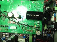
The measurement is taken from test pins and referenced to ground if I recall.
Depending on the PSU you use and ground wiring, 0V ref. might fluctuate a little, giving you
strange results, even measuring after the caps (whilst measuring between output of caps and ground).
I don't recall if there's an "output cap bleeder" on schematic, a high value R between cap out and ground, ensures that cap is properly DC loaded to block output DC.
Absolute tolerable DC at the output depends on the preamp you use after. If coupled with input cap you shouldn't have to worry ...
Best,
nAr
I don't agree 🙂Paper caps sound awful in low-voltage applications. Use the K73.
I use the MBGO2 type as output caps on my D1 I/V stage, and other line level outputs sources as primary tweaks. But I agree that I had to test many other different types before my definite choice 🙂
I just like the sound AND price (at the time I bought them) 😉
Anymay, Siberia goes for Mundorf caps (rich guy hu hu hu) 🙂
And we won't launch a discussion on components, shall we ? 😉
Last edited:
The R you are talking about is a 100k resistor.
Oups, yep, you're right 😉
Bonjour les gars, 
Thanks for your input.
Very interesting thoughts, Nar, about possible ground fluctuations...
But I'm not sure I can subscribe to the same problem if measured right at the output.
My preamp is a DCB1. No input cap...
And I'm not rich 😕 just showing off my spares bought some years ago 🙄 I still have to find time and a way to install those chunkies.
Just twist the wires and it will be ok .
To be sure, you can route wires from bottom, near the case, a ground plane.
But shorter is better, as usual.
To be sure, you can route wires from bottom, near the case, a ground plane.
But shorter is better, as usual.
- Home
- Amplifiers
- Pass Labs
- Pearl Two