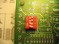
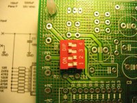
SW1 is used to set the load.
The easiest is to use 1 switch.
SW1 1 R6 1000R
SW1 2 R7 825R
SW1 3 R8 475R
SW1 4 R9 249R
SW1 5 R10 100R
SW1 6 R11 47R5
SW1 7 R12 24R9
SW1 8 R13 10R
You can of course use multiple resistors to parallel them and get values in between.
I wont make a chart of this.
You can see the Aleph Ono user manual.
Calculate yourself or use a multimeter.
1 A groundplane should always be massive and make a good ground. Are you really sure about that, lower capacitance?promitheus said:the meshed ground plane has a few advantages over solid plane.
1. lower stray capacitance
2. pcb remains flat
2 That may be true but I haven't got any problems with massive groundplanes and machine soldering.
promitheus said:the meshed ground plane has a few advantages over solid plane.
1. lower stray capacitance
2. pcb remains flat
1. Ignorable
2. It does anyways
3. High inductance/impedance
4. Compromized (frequency limited) shielding capabilities
But you don't APPLY the copper, you ETCH it away. How can you save on something you have to remove?
If you have doublesided boards you do really add copper! The process is not like when you do it at home.
Double sided laminates are standard. They come with Cu on both sides. You only bond layers of Cu on multilayer boards with prepregs in between. Regardless of the process used, you still have to etch away Cu to make the mesh pattern.
... some but not much.... back to the topic. 🙂promitheus said:do you guys have a point about this?
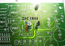
Some people are asking about the placement of the Q5 Transistor.
If you are using a BC550 just follow the layout.
If you are using the 2SC1844 from the KIT you need to solder it like in the photo. because it has a different pin out.
You need to move one position up.
Check the new Photo to see the 2 different pinouts.
If you are using a BC550 just follow the layout.
If you are using the 2SC1844 from the KIT you need to solder it like in the photo. because it has a different pin out.
You need to move one position up.
Check the new Photo to see the 2 different pinouts.
Attachments
Promitheus,
I received my MC boards/kit yesterday and started assembly. We are on our 4th of July holiday today so I plan on trying to get my boards built and tested. Hopefully there won't be any fireworks!
Thanks for all your work!
Nate
I received my MC boards/kit yesterday and started assembly. We are on our 4th of July holiday today so I plan on trying to get my boards built and tested. Hopefully there won't be any fireworks!
Thanks for all your work!
Nate
My Pearl "MC" is up an running! I have a Shelter 301 0.3mV MC cart and things are sounding pretty good! It is set with a loading of 100ohms and with a gain setting of -10 which seems to be the best setting so far.
Cheers
Nate
Cheers
Nate
- Status
- Not open for further replies.
- Home
- Amplifiers
- Pass Labs
- Pearl MC Pre-Preamp