It s a little complicated, so first they need some wood which is dry enough, so it won't shrink anymore.
The next you can see, also at the pictures you uploaded, they didn't use one solid piece, they use several.
There will be a maximum of movement in every wooden slat, also it could bend over time, the wider the given piece of wood is, the more it could bend over the time because of humidity and so on. -> But it will just bend with the fiber direction, not against.
If you use several and glue them together you will minimize the range of this movement.
The brace would also help a lot and what also help to strengh the bonding are so called lamellos, I also used them, they help a lot to keep the wood in its place.
Last edited by a moderator:
Thanks @Qualle, I think I will go with a smaller one
Thanks @Hondasnl for the effort to get a viable DIY Sibellius!

I'm thinking to order the wood for 1 pair of cloned Sibelius CG.
Thinking of a combination of solid Oak and Maple.
Thinking of a combination of solid Oak and Maple.
Attachments
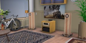
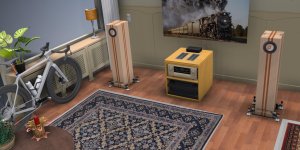
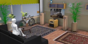

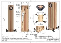
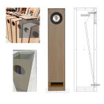
@Hondasnl I believe some of your distances in your initial design needed updating. I created a Blender object and tried to match the orientation of some of the Sibelius pictures.
I came up with the following changes:
1. Woofer needs to go lower 1cm
2. Bottom opening needs an increase of ~1cm
3. Internal wood divider needs quite a bit of lowering.
I can share the blender file if you want, but bellow is an overview of the overlaps & distances.
I think I will build it with 25mm plywood panels, use wood screws to stabilize the whole box and glue 8mm plywood panels to all the sides (other than the bottom that is 2X 25mm) to increase the thickness to 33mm.
Attachments
Last edited:
For some reason I had missed your posts. Great work!When I first want to start this build I didn t fully read this thread, I just found the sketch and compared to several pictures of the originals, where it also seem to be lower, so I changed.
Later I also want to try how the sound change if I build this part a little higher.
Please correct me if I m wrong, but to lower this part could tend to higher port resonances ?!
In my modified design, I had to lower it about ~40mm (but I also lowered the woofer by 10mm). Not sure how it will affect the sound...
@Hondasnl I believe some of your distances in your initial design needed updating. I created a Blender object and tried to match the orientation of some of the Sibelius pictures.
I came up with the following changes:
1. Woofer needs to go lower 1cm
2. Bottom opening needs an increase of ~1cm
3. Internal wood divider needs quite a bit of lowering.
I can share the blender file if you want, but bellow is an overview of the overlaps & distances.
I think I will build it with 25mm plywood panels, use wood screws to stabilize the whole box and glue 8mm plywood panels to all the sides (other than the bottom that is 2X 25mm) to increase the thickness to 33mm.
Hi Kotlos,
Thx!
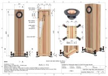
I also checked again.
It seems that there are 2 versions with different heights of the opening..
The bottom opening are different I can see on the comparative photos below.
I have changed it to 60mm and 60mm from the bottom.
The driver I have lowered 5 mm.
Attachments
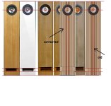
That's interesting with the two versions... The Sibelius -L line also looks like having a smaller opening?
Do you think the internal wave guide will have a big role in the response? How did you find out its position in your current design?
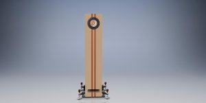
Also do you have a part# for this amazing metal base?
Do you think the internal wave guide will have a big role in the response? How did you find out its position in your current design?
Also do you have a part# for this amazing metal base?
These are really good (not all terminals can go through 18mm+ material). And sure ready if you get the crimps as well. Jantzen binding posts.
@tigeranand what amp are you using?
@tigeranand what amp are you using?
I'm not sure that placement of the driver is something that one should guess without simulation of response. Port placement and area is also quite important, so some calculation would be wise
guess without simulation of response
The whole thing should be simulated.
Guessing the design as has been happening is a crap-shoot.
dave
Hi Dave dont be soo negative haha. Please can you simulate.
Edit: It will not sound that bad without simulation.
Edit: It will not sound that bad without simulation.
Last edited:
From what I understand, if it was possible for the simulations to be accurate enough, then there wouldn't be much point for these speakers would it? The process of original designer was that measurements and simulations got him up to a point, but after that he needed to use his ears to modify the design for a pleasant listening experience.
So if we are trying to mimic his design, simulations are unlikely to get us there.
As @Hondasnl mentioned, if there are simulation software that by feeding some parameters can actually match the measured frequency response of these speakers, then sure lets use them. But has that ever worked with most speakers? By than I mean matched simulated and measured frequency response. And this is an honest question...
Last edited:
simulations are unlikely to get us there
Actually you might be surprised. Modern tools allow very accurate sims. A good sim gets you at least into the ballpark (a good one can be right on).
For instance we have built many of Scott’s designs. From sim to real and rersults match sims so well i have no issues with building anything ne designs and expecting them to be good.
The model you are using (the Sibelius) uses different drivers than any of us have any access to.
dave
You have box dimensions from drawings and TS for Alpair 10.3 so why not do sims before cutting wood.
Hi Dave, can you simulate the original 10.3 and 10.2 for us?
You know the specs.
It is not my intention to build a commercial speaker 😉.
You know the specs.
It is not my intention to build a commercial speaker 😉.
Hello Dave,
Thank you for the "enlightenment", I fully agree with your "statement". None of us will ever get a sticker with "Pearl Acoustic- Highend Loudspeakers"!
Regards from the old world
Stefan
Thank you for the "enlightenment", I fully agree with your "statement". None of us will ever get a sticker with "Pearl Acoustic- Highend Loudspeakers"!
Regards from the old world
Stefan
- Home
- Loudspeakers
- Full Range
- Pearl Acoustic Sibelius