Hi Werner,
I didn't see the technic of making a PCB from a laser printed image mentioned anywhere in this thread until my last post so i assumed the layout had an error. Usually when i see a PCB image i assume that it is represented as is the final outcome. My bad.
Teemu K
I didn't see the technic of making a PCB from a laser printed image mentioned anywhere in this thread until my last post so i assumed the layout had an error. Usually when i see a PCB image i assume that it is represented as is the final outcome. My bad.
Teemu K
hey teemuk
imagine that the pcb is a glass sheet and the components on it top side and tracks in bottom.so draw lhe layout in a cad program like eagle cad,select bottom copper layer to connect the components.take print out in monochrome on sheet and iron it as it is.u will get the tracks right this way.if u still have probs. take a transparancy(used in projecters) and print the tracks on it and use your wits to to understand that in which way u should iron.
imagine that the pcb is a glass sheet and the components on it top side and tracks in bottom.so draw lhe layout in a cad program like eagle cad,select bottom copper layer to connect the components.take print out in monochrome on sheet and iron it as it is.u will get the tracks right this way.if u still have probs. take a transparancy(used in projecters) and print the tracks on it and use your wits to to understand that in which way u should iron.
Hi Sagarverma,
I catched the point already and i'm familiar with this laser print technique of making boards - i just didn't see it mentioned anywhere in this thread before i posted my "correction" to the layout.
Anyway, i feel that ironing a board for several minutes (the copper layer heats up) is not a very good practice and can easily be done wrong by someone who is doing it the first time. Also, not that many people have access to laser printers.
Since light sensitive boards cost a lot, here is my way of making (simple) PC boards. (Note that these instructions are for people who have no experience of making PCB's):
1. Glue a paper with a printed image of the (final) layout to the copper side of the board. From downside it should show component pin order as a mirror image. You can use tape also but i feel that glue holds more firmly.
2. Drill holes to the board according to layout. Drilling from the copper side is essential since copper layer cracks easily.
3. After drilling, remove the paper with layout. If you used paper glue soaking in water works fine. Be careful to remove all the glue also.
4. Use a permanent marker to draw the copper tracks between holes. (This is where you need a solid hand and realize why this is worthwhile only for simple layouts.)
5. Etch the board.
Teemu K
can anyone trace slowfly,where is he?what has been the result ofhis project.................................................etc.
----------------------------------------------------
****@
----------------------------------------------------
****@
HELLO!!
Now im back!! I have got other things on my mind😉
BuT now i think the projekt is ready!
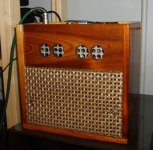
So now i have build a amplifier based on a LM386 with a pcb from a projektbook from school...
And i took a old PC-speaker and builded a small speakerbox that woorks really good 😀
Here is a picture :
Thanks again for all the wonderful help !!!!!!!!!!!
//Elias
Now im back!! I have got other things on my mind😉
BuT now i think the projekt is ready!
So now i have build a amplifier based on a LM386 with a pcb from a projektbook from school...
And i took a old PC-speaker and builded a small speakerbox that woorks really good 😀
Here is a picture :
An externally hosted image should be here but it was not working when we last tested it.
Thanks again for all the wonderful help !!!!!!!!!!!
//Elias
good work slowfly,great looking.
congrats!keep the good work goin
--------------------------------------------------
😱 EARTHQUAKE STRUCK TWO DAYS BACK AND THIS WAS MY STATE THEN!!
congrats!keep the good work goin
--------------------------------------------------
😱 EARTHQUAKE STRUCK TWO DAYS BACK AND THIS WAS MY STATE THEN!!
I wouldn't bridge LM386. I did that and blew two of them in seconds after playing really loud 😀
BTL with 8 or 16 ohms on 5V is OK, but NOT on 9-12V 😱
LM386 is a good little chip though. Makes a good headphone amp too.
For more power, get a cheap 12V BTL car stereo amp chip, and with some good batteries, it will be plenty loud, put a few good boomboxes to shame!
BTL with 8 or 16 ohms on 5V is OK, but NOT on 9-12V 😱
LM386 is a good little chip though. Makes a good headphone amp too.
For more power, get a cheap 12V BTL car stereo amp chip, and with some good batteries, it will be plenty loud, put a few good boomboxes to shame!
- Status
- Not open for further replies.
- Home
- Amplifiers
- Chip Amps
- Pcb to Stereo Amp LM386