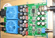
I completed the assembly of my Headphone DAC. Check the picture. I had a few problems to get the processor programmed correctly. Here my own, more detailled, programmation check list. Follow these steps and it will work like a charm:
(i) Don't connect the AVRISP mkII module to the USB Port
(ii) Install the AVR Studio 4 and upgrade and the USB driver for the AVRISP mkII module
(iii) Plug the AVRISP mkII module (green led on module turns on)
(1) Start AVR Studio and Press the AVR Chip Icon (in Black), select AVRISP mkII programmer and ATMega8 as the device type.
(2) Under the Advanced tab in the Signature Bytes, press the "Read" button to read the device signature
(3) Under the Fuses tab, make sure the fuses are programmed as follows and hit Program:
[ ] Reset Disabled
[ ] Watchdog timer Always On
[X] SPI downloading enabled (if it's grayed out, ignore)
[ ] Preserve EEPROM
[X] Boot flash size = 128
..
[ ] Boot Reset Vector Enabled
[ ] CKOPT fuse
[X] Brown out at 2.7V enabled
[X] Brown out detection enabled
...
[X] Int RC Osc 4MHz, 6CK + 4ms
(4) Under the Board tab in the Voltages area, press "Read Voltage", now VTarget should read 3.3V
Under the Board tab in the Osc & ISP Clock area, in the ISP Freq section select 1Mhz (1/4 of the target clock (the ATMEGA8 is running at 4Mhz), press the "Write" button.
(5) Under the Program tab in the Flash area, point that at your .hex file and hit Program.
Attachments
First listening impressions are very good. I compared it to my present test setup: ML37 Transport, Guido Tent Super Tube Dac and PSAudio GCHA Headphone Amplifier. It used the same ML37 to drive the Headphone DAC.
I must say that it I got maybe 80-90% of the sound of my much more expensive test setup. There is a slight more trace of sibilance, bass are not as much powerful and space is less airy, but all in all it is an excellent DAC and a very nice headphone Amp. Very impressive. Thanks GMarsh for sharing your very nice design.
I must say that it I got maybe 80-90% of the sound of my much more expensive test setup. There is a slight more trace of sibilance, bass are not as much powerful and space is less airy, but all in all it is an excellent DAC and a very nice headphone Amp. Very impressive. Thanks GMarsh for sharing your very nice design.
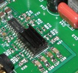
The only detail that trouble me is the heat management of this PCB. The 3.3V regulator is too hot to touch (temp > 55C). The headphone amp IC is also very hot. I added a heatsink to it. I glued it in place using epoxy glue. Not a perfect heat transfer but better than nothing. By the way soldering all these very small leads was not a ride in the park 🙄 Before powering the board I checked all the circuit using an ohmeter. I had only one IC pin that was not making contact. Not bad for a soldering job done at 10PM 😉
Attachments
I added small heatsinks to the four voltage regulators. The 3.3V was too hot for my taste. If it is not enough I will arrange for this regulator to use the casing as heatsink. I will also use a case with some ventilation and a Power-On switch.
Attachments

Algar_emi,
great to hear you got your unit working. Can you verify with your unit,
the power on issue I had seen with mine ?
I'd love to respin this CCA and do another improved version of it but I
have not much time these days, too many other projects to look after 😀
Cheers
Kay
great to hear you got your unit working. Can you verify with your unit,
the power on issue I had seen with mine ?
I'd love to respin this CCA and do another improved version of it but I
have not much time these days, too many other projects to look after 😀
Cheers
Kay
I'll check and report back. By the way I tried a the Grado SR125 and the Sennheiser HD600 with equal good result.
Algar,Algar_emi said:I added small heatsinks to the four voltage regulators. The 3.3V was too hot for my taste. If it is not enough I will arrange for this regulator to use the casing as heatsink. I will also use a case with some ventilation and a Power-On switch.
I did not have an overheating issue with the 3.3V regulator on any of my three builds. You may want to re-check the 3.3V output first, then all the component values and soldering associated with the regulator.
The headamp IC was hot, but not uncomfortably hot. Did you solder the power pad to the PCB? It takes a lot of heat to do that....I was affraid I was going to burn it up, but it worked fine.
Have you tried your line output circuit yet?
Robert
Yes, I tried it and it sound very good. No I didn't solder the headphone IC bottom power pad to the PCB, I though they were only suppose to touch. I'll solder it tonight.
When I assembled the PCB, I did first all the smd parts and checked all connections. I had no solder bridge and only one pin was not making contact. Then after I was sure that all the circuit was correct, I installed the regulators and the rest of the discrete parts. Then I power the PCB and checked the supplies. All the supplies voltages were Ok. I programmed the processor and the headphone DAC worked perfectly, except for the heat issue. I know now why the heaphone Amp IC was hot, I'll correct that.
Did you have install bypass film caps on the voltage regulators output caps? I have 0.047uF MKP film installed, lowering even further the caps ESR. Maybe these caps are causing problem with the regulators. I'm also using Panasonic FC low ESR caps for the supplies.
Was is your total AC Current at the line input for your DAC?
My line output is not completed yet. The PCB is done but I still need to test the op-amp resistor values. I just bought the Hammond enclosure. I'm working to complete my AYA-DAC to test the options pcb that I sold. I also started a group buy for Maxon motor.
Algar_emi said:
Did you have install bypass film caps on the voltage regulators output caps? I have 0.047uF MKP film installed, lowering even further the caps ESR. Maybe these caps are causing problem with the regulators. I'm also using Panasonic FC low ESR caps for the supplies.
Was is your total AC Current at the line input for your DAC?
Sorry for the delay in responding. If I understand your question regarding the PSU output caps, I used 220uf 35V FM Series caps at C13 16 19 & 22, and I did install .047uf 50V ceramics at the optional caps C44 45 46 & 47.
I have not measured the current draw at the mains input.
Robert
Here's some clarification on hot parts:
With the LM1085, Tj(max) is 125C and Rjc is 3degC/watt. Case to ambient for a TO-220 is about 60 degrees/watt - high enough to assume that the case temperature is almost equal to junction temperature. So even if the case is at 120C, which is "you'll burn your finger and hear a sizzle when it happens" territory, the LM1085 is still operating within spec.
The TPA is well heatsinked but still well within spec.
Silicon can handle much higher temperatures than your finger, so using your finger as a temperature gauge is being *very* conservative. 😀 Unless you do something like mount the amplifier in a plastic case, don't worry about part temperatures.
I'll use a digital thermometer (Fluke) to check the temp 😉
Except for my Class-A amps and my tube circuits, I like my circuits to be colder. I'll check the specs in details.
Thanks for the precision.
Except for my Class-A amps and my tube circuits, I like my circuits to be colder. I'll check the specs in details.
Thanks for the precision.
Hi Gmarsh. I guest you were right. The temperatures are not so bad after all. Here my results (with my small heatsinks installed but inside the enclosure):
3.3V: 61C, 5V: 50C, +12V: 53C, -12V: 46C
TPA6120: 48C (IC heat pad still not soldered)
Thanks for the info.
3.3V: 61C, 5V: 50C, +12V: 53C, -12V: 46C
TPA6120: 48C (IC heat pad still not soldered)
Thanks for the info.
Just a bump.
Oh man, I can't believe there is so little interest for such great DAC.
Cheers
Kay
Oh man, I can't believe there is so little interest for such great DAC.
Cheers
Kay
I'm personally waiting for a microcontroller to come out which features high-speed USB 2.0 and an I2S capable codec interface, and isn't in a BGA package so it can be hobby-built.
There's a bunch of new ARM 'Cortex' stuff starting to enter the market right now, hopefully one of these will fit the bill.
When that happens, the HD-2 will be designed, an end-clocked 192KHz-capable USB DAC. 😀
There's a bunch of new ARM 'Cortex' stuff starting to enter the market right now, hopefully one of these will fit the bill.
When that happens, the HD-2 will be designed, an end-clocked 192KHz-capable USB DAC. 😀
AVR32 or ARM7TDMI
Hi qmarsh and guys,
I started working on similar project as DAC HD-1, but with SD card as a sound source. Even though my computer is quite quiet (HP Compaq nc6230), still is not sufficient for a night listening. The two advantages of SD card are that for listening I don't need computer and there are no noisy parts (like HDD, CD drive,...).
The player is only at testboard (SD connector is at the moment not shown in picture). SD card is read with ATmega88 at 3,3V and ~12MHz XTAL. DAC is TDA1545. It is not a great DAC, but for test digital parts (reading PCM data from SD Card and generating digital signal like I2S for DAC) is OK. The SW is done in C with some routines in assembler language.
I thing that better solution is to use for example ARM7TDMI with DMA (or incoming AVR32 with USB) at ~45MHz clock. There are next possibilities of decoding FLAC or APE files - you need only SW upgrade. (BTW I have heard that ARM7 is capable decoding of MP3 too). ARM7 have DMA access and there is (theoretically) no problem of generating signal data for DAC - I don't need I2S supported by hardware because of DMA in ARM7.
Do anybody have interest for cooperate on this project? 🙂 I am not so good as qmarsh in PCB design, for example I can make SW for this project.
SD card player
Hi qmarsh and guys,
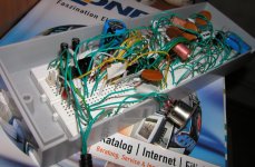
I started working on similar project as DAC HD-1 a few weeks ago, but with SD card as a sound source. Even though my computer is quite quiet (HP Compaq nc6230), still is not sufficient for a night listening. The two advantages of SD card are that for listening I don't need computer and there are no noisy parts (like HDD, CD drive,...).
The player is done only at testboard today (SD connector is not shown in picture at the moment). Signal path is SD CARD – ATmega88 – TDA1545 – NE5532 - Headphones. SD card is read with ATmega88 at 3,3V and ~12MHz XTAL. Analog parts like DAC TDA1545 and NE5532 are not a great, but for test digital parts (reading PCM data from SD Card and generating signal like I2S for DAC) is OK. Software is done in C with some routines in assembler language.
I thing that better solution is to use for example ARM7TDMI with DMA (or incoming AVR32 with USB support) at ~45MHz clock. There are perhaps next possibilities of decoding FLAC or APE files in the future - you need only SW upgrade. ARM7 have DMA access and there is (theoretically) no problem of generating signal data for DAC - I don't need I2S supported by hardware because of DMA in ARM7.
Do anybody have interest for cooperate on this project? 🙂 I am not so good as qmarsh in PCB design, but I can make SW for this project.
Hi qmarsh and guys,
I started working on similar project as DAC HD-1 a few weeks ago, but with SD card as a sound source. Even though my computer is quite quiet (HP Compaq nc6230), still is not sufficient for a night listening. The two advantages of SD card are that for listening I don't need computer and there are no noisy parts (like HDD, CD drive,...).
The player is done only at testboard today (SD connector is not shown in picture at the moment). Signal path is SD CARD – ATmega88 – TDA1545 – NE5532 - Headphones. SD card is read with ATmega88 at 3,3V and ~12MHz XTAL. Analog parts like DAC TDA1545 and NE5532 are not a great, but for test digital parts (reading PCM data from SD Card and generating signal like I2S for DAC) is OK. Software is done in C with some routines in assembler language.
I thing that better solution is to use for example ARM7TDMI with DMA (or incoming AVR32 with USB support) at ~45MHz clock. There are perhaps next possibilities of decoding FLAC or APE files in the future - you need only SW upgrade. ARM7 have DMA access and there is (theoretically) no problem of generating signal data for DAC - I don't need I2S supported by hardware because of DMA in ARM7.
Do anybody have interest for cooperate on this project? 🙂 I am not so good as qmarsh in PCB design, but I can make SW for this project.
Attachments
Am I too late to get a board?
I was looking around for another project and saw this one. It looks very nice. Am I too late to the party? Are there any extra boards? If so, I'd like one. Tell me who to contact and I will.
thx,
Tom
I was looking around for another project and saw this one. It looks very nice. Am I too late to the party? Are there any extra boards? If so, I'd like one. Tell me who to contact and I will.
thx,
Tom
2 boards for sale.
I never got around to finding the time to build the two boards I purchased. I'm a little disappointed, but maybe I can make someone else happy.
2 boards, $30US each plus shipping.
PM me. First come first served.
Ciao
I never got around to finding the time to build the two boards I purchased. I'm a little disappointed, but maybe I can make someone else happy.
2 boards, $30US each plus shipping.
PM me. First come first served.
Ciao
- Status
- Not open for further replies.
- Home
- Group Buys
- PCB Group Buy for the "DAC + headphone amp" Project