No one has been willing to undertake another group buy, although Gary has made the files available.tobias_svensk said:I would be in too. 🙂
Also, Gary did not have the time to pursue his desired modifications, so the last effort sort of died out.
If ever revived, I would be in for a few more boards. I love the two I built (my sone has one), and I have never gotten around to debugging my third one.
Robert
I still have my untouched board, I've had to buy a new table saw, lots of stuff and had thousands to spend on something that happened recently and don't think I will be able to build this. If anyone is interested in the board PM me.
Josh
Josh
I have one board from the group buy. I don't think I have time to finish this project. If you are interested, please email me.
Thanks
Thanks
Dougie086,Dougie085 said:Ah your going to buy both? lol....
I only needed one. You can try to contact EdJosh23...he hasn't responded to email, and the administrator currently has IMs turned off.
Robert
If someone still has a pcb available, I will take one for sure. I bought all the parts because I was planning for the next group buy that was cancelled. I really want to complete this project. Waiting for you reply guys. Thanks in advance...
Please count me in for one board if Gary or someone else wants to improve the design with the power on reset chip which addresses the brown out issue, and perhaps a relays which switches the headphones on after power up to avoid the annoying 'thumb' which could possibly damage more expansive headphones.
Also a power on switch on the front panel would be very welcome.
Cheers
Kay
Also a power on switch on the front panel would be very welcome.
Cheers
Kay
Hello guys. Does anyone know what exactly causes the thump when first powered on? Is this a problem every board has?
Hi Ghetto,
I believe this is 'thump' problem is by design, because both of the units I build have this behavior.
Some chips do have a build in 'thump' suppression, but I am not sure if these chips that were used here
do have that or if it is utilized. With audio amplifiers it is quite common to have a relays on the output
which turns on delayed to avoid that. (as a poor mans solution, but quite effective tho)
Cheers
Kay
I see... So just muting the PCM1792 for half a second or so when the board first powers up is probably not going to solve the problem.

I don't think I'll make any more changes to the design in the forseeable future... I'm now a homeowner! I've got endless projects around the house to undertake now. Drains to dig, steps to build, wasp nests to destroy... it's a full time job. Plus the mortgage and bills don't really facilitate working on electronic projects with multilayer PCBs.
kct, you've done a pretty good job on your own board so I'll leave any modifications in your capable hands. 😉
As for the turn-on thump, there's not much you can do with the design to fix it other than add a relay to the output.
kct, you've done a pretty good job on your own board so I'll leave any modifications in your capable hands. 😉
As for the turn-on thump, there's not much you can do with the design to fix it other than add a relay to the output.
I completed the assembly of my Headphone-Dac and tested all the DC supplies and connections. Everything seem to be Ok so far. I'm waiting for the programmer to arrive and download the processor code.
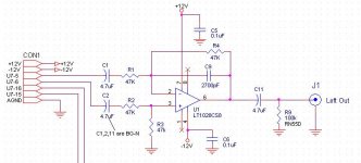
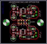
I want to add if possible a line output option to this excellent dac design. I'm planning to take the audio signal from the Op-Amps U6, use BG-N coupling caps to remove the big DC offset present there, and use a good quality differential Op-Amp to get a single-ended output.
I'm may need to paly with the resistors values to get the correct signal output amplitude.
Here the prototype schematic, just one channel illustrated.
Attachments
Algar,
That looks interesting....please let us know how it works out.
I just finished up my third HD-1. I gave one away, so I now have a matched pair....one black, one silver. I added a power switch and power LED since I only use them occasionally.
They sound very good. No audible noise, and very full sound.
Robert
An externally hosted image should be here but it was not working when we last tested it.
An externally hosted image should be here but it was not working when we last tested it.
- Status
- Not open for further replies.
- Home
- Group Buys
- PCB Group Buy for the "DAC + headphone amp" Project