So far you guys are missing ...
plopla: 4
audiofanatic: 20
woody: 4
I'll send you a PM to verify you are still interested. we are at 205 boards confirmed.
and two for me:
superfigone: 2
thanks
So ... total number of confirmed boards is 213. Audiofanatic confirmed 20 (payment still pending). I'll order 240 boards so a few extra will be available. Most probably I will have them shipped to USA (no VAT) and every board will be cheaper than 3.7$ we are using as preliminary price. We will know that tomorrow.
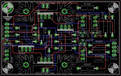
Attached you'll find the last revision of the board, let me know if you have comments or suggestions
Attached you'll find the last revision of the board, let me know if you have comments or suggestions
Attachments
Paid
Ciao Gianluca,
Sorry for the delay, payment sent a few minutes ago 😉
Ciao e Grazie ,
Audiofanatic 🙂
Ciao Gianluca,
Sorry for the delay, payment sent a few minutes ago 😉
Ciao e Grazie ,
Audiofanatic 🙂
So ... total number of confirmed boards is 213. Audiofanatic confirmed 20 (payment still pending). I'll order 240 boards so a few extra will be available. Most probably I will have them shipped to USA (no VAT) and every board will be cheaper than 3.7$ we are using as preliminary price. We will know that tomorrow.
Attached you'll find the last revision of the board, let me know if you have comments or suggestions
for my is good, if you could make the biggest tracks is better
Ordered. They will check the design and confirm the quotation tomorrow. Price so far is 704.2$ for the boards and 86$ for the shipping. That makes a crude price per board of 3.30$. There should be enough headroom to cover mailing costs too with the preliminary price of 3.7$ we were considering. I ordered 240 boards (vs the 233 confirmed) so sigfire can jump on in case he decides so or I (or anyone else) will buy the extra boards.
Boards will be 1.5mm thick, 2oz copper, ENIG finish (gold plated), white silkscreen on black mask.
Tracks are 16mils which is 20x the minimum required for 200mA currents and 10degC temp increase. Increasing the width would require a larger board. IXTP can be operated at 100mA maximum! DN2540 can go up to 500mA in TO220 (8x headroom in this case).
Attachments

Silvercircuits started the production this night.
Alberto, I'd give precedence to sigfire (on hold as he is still waiting for the FETs) if he doesn't join 4 extra boards go to you.
Alberto, I'd give precedence to sigfire (on hold as he is still waiting for the FETs) if he doesn't join 4 extra boards go to you.
Gluca - fantastic PCB, very good work! If there will be any spare boards, then I'll take the rest. Please contant me PM if it is possible.
Best wishes,
Radek
Best wishes,
Radek
Hi Radek ... we'll see. I ordere only a very few extra.
OK, thanks Gluca and remember about me.
Am I correct, that up to 400V B+ there is no problem with substitute DN2540-N5 instead 1000V IXYS IXTP 01N100D without any elements change?
Is LND150 substitutable in this circuit with DN2540-N5 too (despite their differences)?
(I have many DN2540-N5, so for me they are "natural" ;-) )
Yes. DN2540 is ok up to 400V.
LND150 is TO92 so you might replace it with DN2540N3. DN2540N5 is TO220 so you cannot use it.
LND150 is TO92 so you might replace it with DN2540N3. DN2540N5 is TO220 so you cannot use it.
As used as CCS with IXZY and DN2540N3.The DN2540N3 can take 400v so guess 400v is the limmit the CCS can take?
If you use DN2540N5 at Q100 and Q200 (see my schematics) the board will take 400V max. Keep in mind that your B+ must be higher than the plate voltage (if you are using the CCS as plate load): plate voltage (example 150V) + peak signal voltage swing (ex. 50V) + headroom (ex. 20V) ... so you end up with a B+ of 220V minimum to load a 150V tube.
If you are using IXTP01N100D at Q100 and Q200 you can go up to 1000V as the upper FETs (Q100 and Q200) are taking all the voltage drop.
Lower FETs will only see a little Drain-Source voltage drop so DN2540 are fine there.
Clearly you need to stay safe so dissipation and max voltage (I'd derate DN2540 and IXTP by 20% as a minimum) must be kept under control.
Thanks for explaining that.
Edit:Maybee you could explain how the VCCS works I think inkluding myself there are some that don know how it works.
regards
Edit:Maybee you could explain how the VCCS works I think inkluding myself there are some that don know how it works.
regards
Last edited:
To make the board work as VCCS you need to replace the jumper JP3 and JP1 with a 0.1u high voltage cap. Q102 (and Q202) needs to be installed too and it works as a CCS and sets the voltage at the gate of Q101 (and Q201) hence the voltage at its drain is fixed.
To make the board work as VCCS you need to replace the jumper JP3 and JP1 with a 0.1u high voltage cap. Q102 (and Q202) needs to be installed too and it works as a CCS and sets the voltage at the gate of Q101 (and Q201) hence the voltage at its drain is fixed.
Where would one typically use a VCCS as opposed to a CCS?
Thanks in advance.
nothing, just one more possible use, a la John Swenson... 🙂what's wrong with vacuum-state pentode. i'll use VCCS in single ended amps PSU.
A lot of info about VCCS is in this topic: http://www.diyaudio.com/forums/tubes-valves/140699-anti-triode-sepp-how-do-best.html
@UnixMan - do you mention this regulator? The Swenson Regulator
@Gluca - what are you observations about use of VCCS in PSU. How it compares with typical MOSFET capacity multiplier in PSU?
What are your observations of use VCCS as active anode load?
@UnixMan - do you mention this regulator? The Swenson Regulator
@Gluca - what are you observations about use of VCCS in PSU. How it compares with typical MOSFET capacity multiplier in PSU?
What are your observations of use VCCS as active anode load?
- Status
- Not open for further replies.
- Home
- Group Buys
- PCB for cascoded IXYS CCS (tube)