Hi,
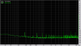
your sound card shows a significant 3rd harmonic at 180Hz and another at the 9th.
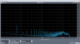
Why does your amp show hum and buzz all the way through the spectrum?
Is this a test set up artifact or is it coming out of the amplifier?
your sound card shows a significant 3rd harmonic at 180Hz and another at the 9th.
Why does your amp show hum and buzz all the way through the spectrum?
Is this a test set up artifact or is it coming out of the amplifier?
AndrewT said:Hi,
your sound card shows a significant 3rd harmonic at 180Hz and another at the 9th.
Why does your amp show hum and buzz all the way through the spectrum?
Is this a test set up artifact or is it coming out of the amplifier?
Hi Andrew,
The soundcard noise is shown below. This is the soundcard itself. Everything is lower than -100db.
The hum or buzz you refer to may be some interference - the DCX2496 is still connected to the remaining channels of the amp and powered, the connection cable is a 2 metre piece of unshielded telephone cable. The amps are very quiet, so no discernible hum or buzz.
I could do everything all neat and scientific, but the picture is clear enough - the amps are performing as predicted.
Compare it to the recent tests of my finished K10A - the magnitude of the hum and buzz is much stronger in that one, yet it is very silent. These peaks are way down.
Attachments
Hi,
are you able to measure the output noise (with shorted input) of both these amplifiers?
I get the impression from your graphs that it is >>0.05mVac
are you able to measure the output noise (with shorted input) of both these amplifiers?
I get the impression from your graphs that it is >>0.05mVac
AndrewT said:Hi,
are you able to measure the output noise (with shorted input) of both these amplifiers?
I get the impression from your graphs that it is >>0.05mVac
I'm too lazy to connect to my scope and I don't have a millivolt meter, but here's what I did - I recorded the output of an amp with it's input shorted. The result is attached and backs up the RMAA result. I used the same telephone cable attenuator rig as before (I need to make something better).
This doesn't show the voltage magnitude but in the next post I will attach a sound clip of this "noise".
Attachments
MJL21193 said:Compare it to the recent tests of my finished K10A - the magnitude of the hum and buzz is much stronger in that one, yet it is very silent.
"Very silent" was the intent, along with the simplest possible HV power supply.
Cheers,
Glen
MJL21193 said:Soundcard THD = 0.0019, therefore the amps THD = 0.0002% (0.0021 - 0.0019 = 0.0002). Very good!
THD's don't add and subtract that way.
G.Kleinschmidt said:
THD's don't add and subtract that way.
Yes, well I figured something was up, but it can't be a whole lot more. What is the actual calculation?
G.Kleinschmidt said:SQRT ( (dist1*dist1) + (dist2*dist2) )
So, 0.0009%, not 0.0002%
Cheers,
Glen
Thanks Glen,
Another factoid to file

I hark back to the early pages of this thread to
this post from darkfenriz:
Going below say 0.02% THD at 20kHz in a design like this is hardy doable. I don't know where these 0.0000x% figures came from.
I guess we did the un-doable. 🙂
In any case, mission accomplished. The amps in the 6 channel case are on constantly - haven't been shut off in months. Totally quiet, stable and they sound sweet to boot.
most/many DMM have a 200mVac scale.MJL21193 said:....... I don't have a millivolt meter,........
The last digit represents 0.1mVac+-0.05mVac.
If the last digit is off then the signal is <0.05mVac.
I suspect your amp reads at least 1 on the last digit (equivalent to 0.1mVac).
and more likely 0.3mVac
This is not a good way to measure noise because most DMMs have a very poor upper audio frequency response. You are effectively measuring the 50Hz to 1kHz band. Even this restricted (but undefined) bandwidth gives a reasonable measure of hum and buzz.
AndrewT said:most/many DMM have a 200mVac scale.
The last digit represents 0.1mVac+-0.05mVac.
If the last digit is off then the signal is <0.05mVac.
My DMM auto ranges but I can set it for mVAC. Doing so, I measured the output at the binding posts with the input shorted. It read 1.8mVAC BUT this is not correct. With the leads of the DMM flying, It shows a fluctuating voltage, not zero and with the leads shorted, It reads 1.7mVAC.
TBH, I don't trust any reading from this at these low voltages.
Did you download and listen to the clip I posted above? That tells much of what you want to know.
does it misbehave like this when on Vac autoranging.MJL21193 said:and with the leads shorted, It reads 1.7mVAC.
TBH, I don't trust any reading from this at these low voltages.
If so you cannot use it for AC voltage measurement.
My non-autoranging DMMs all (3off) show 0.0mVac and 0.0mVdc when the leads are shorted together.
AndrewT said:does it misbehave like this when on Vac autoranging.
If so you cannot use it for AC voltage measurement.
My non-autoranging DMMs all (3off) show 0.0mVac and 0.0mVdc when the leads are shorted together.
I found the "relative" button on the DMM and this zeroes the scale with the leads shorted. With this, it reads 0.1 - 0.2mVAC.
I tried it with my other, cheaper DMM (bought that for it's hfe tester) and the same result after it was zeroed.
How's that?
for a two/multi channel amp in it's casing, that is pretty good.MJL21193 said:it reads 0.1 - 0.2mVAC.
How's that?
Thanks Andrew,
The case is not complete - the top is still open. It will get finished eventually, but I'm planning a change to the original 3 amp modules - I want to replace these with modules made from the new layout. At present, 3 of the modules are the new layout (left channel amps) and for consistency, I'd like to make the change.
Yeah, I'm a sucker for punishment...🙂

Hm I wouldn't be comfortable with the copper component markings, but other than that, they look the sex 🙂
ostripper said:Beautiful
Thanks,
These are to replace the ones in my 6 channel amp.
jaycee said:Hm I wouldn't be comfortable with the copper component markings, but other than that, they look the sex 🙂
No worries jaycee,
The copper silkscreen was closely inspected for shorts and I spent extra time sizing everything to make sure there wouldn't be a problem.
6 done, tested, ready to install.

- Status
- Not open for further replies.
- Home
- Amplifiers
- Solid State
- Patchwork Reloaded: Circuit Optimization and Board Layout.